Available across Canada at these fine distributors
Western Canada
Ontario
Quebec
Atlantic Canada
Come
4 EXPLANATION
Dual Fuel Controls, Yesterday and Today
Oh, how far we’ve come from the earliest days of managing heat pump integration into existing heating systems. By Ian McTeer
10 INSTALLATION Improving Airflow
Correcting common errors on residential forced air HVAC systems, including ducted heat pumps, based on the analysis of a home in the Greater Victoria Region. By Todd Backus, P.Eng
12 EXPLANATION Swing Season Solution
An air-to-water heat pump can satisfy a complete whole home or building comfort solution for all seasons.
Oh, how far we’ve come from the earliest days of managing heat pump integration into existing heating systems.
BY IAN MCTEER
Once fire became a reliable tool for cooking and indoor warmth, our ancestors quickly faced a new challenge: How to control the heat? The most basic control solution for the earliest home dwellers was therefore invented: move away from the fire when you get too hot.
Once castles, huge fireplaces and chimneys came along, sitting in front of a roaring fire stimulated furniture manufacturers to provide a potential solution for out-ofcontrol indoor climate conditions.
Large quantities of wood was burned in fireplaces requiring an excessive amount of air for combustion. This air, entering the room unchallenged by insulation or windows and through every masonry crack and mouse hole, created hurricane force drafts whipping across the floor and through the room to the fireplace, effectively chilling the backs of those seated in front of the fire while the heat from the fire baked their fronts.
To help overcome this discomfort, an English settee took its place in front of the fireplace. This piece of furniture was merely a wooden bench with high sidearms, a solid back and the space between the seat and the floor completely enclosed. This stopped the chilling air from the back but did not reduce the scorching from the front. So part of the heating/ cooling issue was solved. Oh, how far we’ve come.
HEATING AND COOLING TODAY
Jumping ahead, at least a millennia or so, and skipping over HVAC innovations too numerous to mention here, residential cooling combined with heating became ubiquitous in many neighborhoods throughout Canada. Not every climate demands cooling in the summer, but these days with both heating and cooling being delivered from one installed unit, the heat pump, the solution is being embraced.
I became involved with the very first conventional heat pumps moving into our Canadian marketplace because promises of year-round comfort combined with energy savings attracted many homeowners.
Several generations of heat pumps followed along from the 1980’s, each iteration delivering better efficiency with tighter system controls. However, early heat pumps rated for AHRI Region IV had
Friedrich® Endeavor® Line K-Series™
Compatible with nearly any existing R-454B HVAC system—or as a universal replacement—the EcoNet® enabled Friedrich Endeavor Line K-Series RD18AY Universal Heat Pump excels in all install situations.
Friedrich.com/Residential
limited ability to provide the advertised energy savings in Canada and only provided noticeable savings in areas like the banana belt of southwest Ontario and the lower mainland of B.C.
CONTROL STRATEGY
Early heat pump systems, especially those installed as an add-on to a gas, oil or electric furnace, required a specialized room thermostat, outdoor thermostat(s), a relay kit to ensure the components operated in proper sequence and extra power (all explained below):
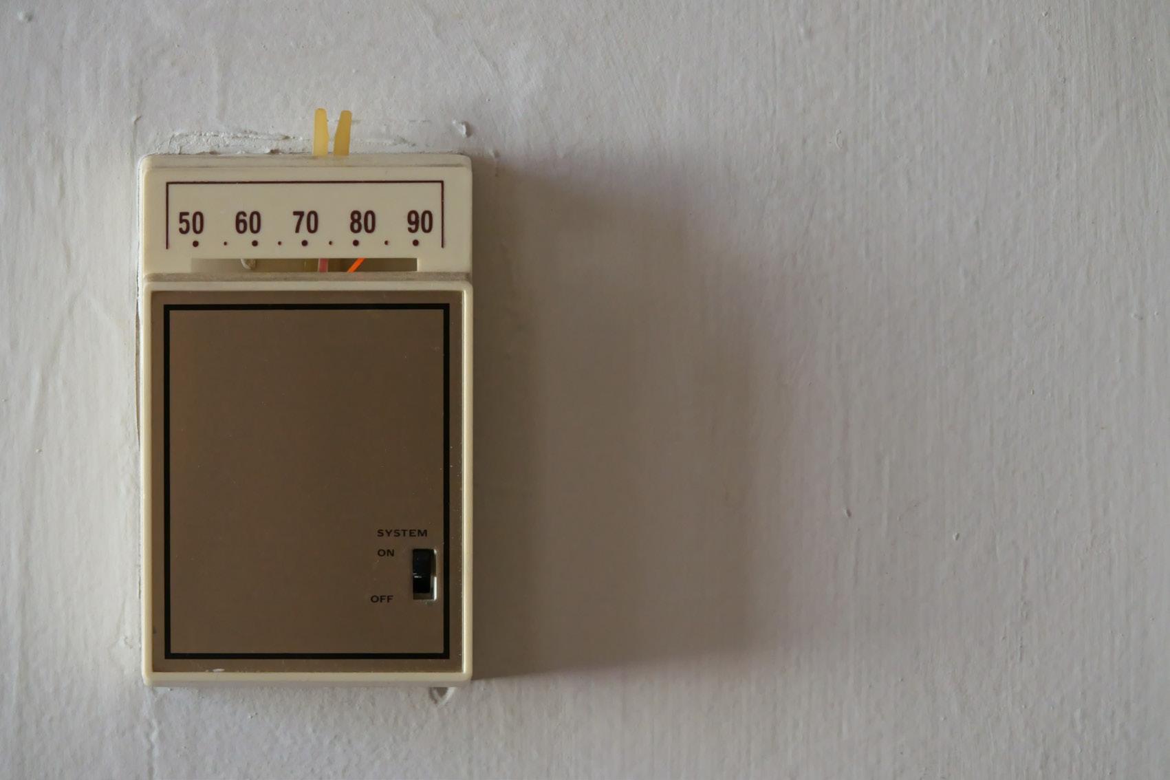
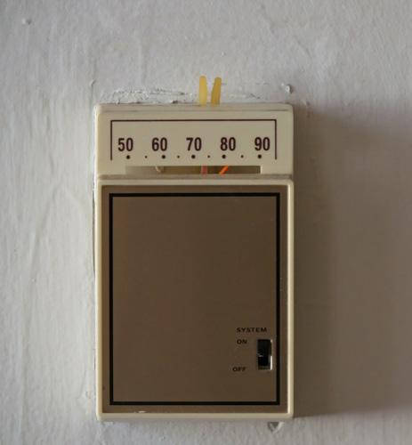
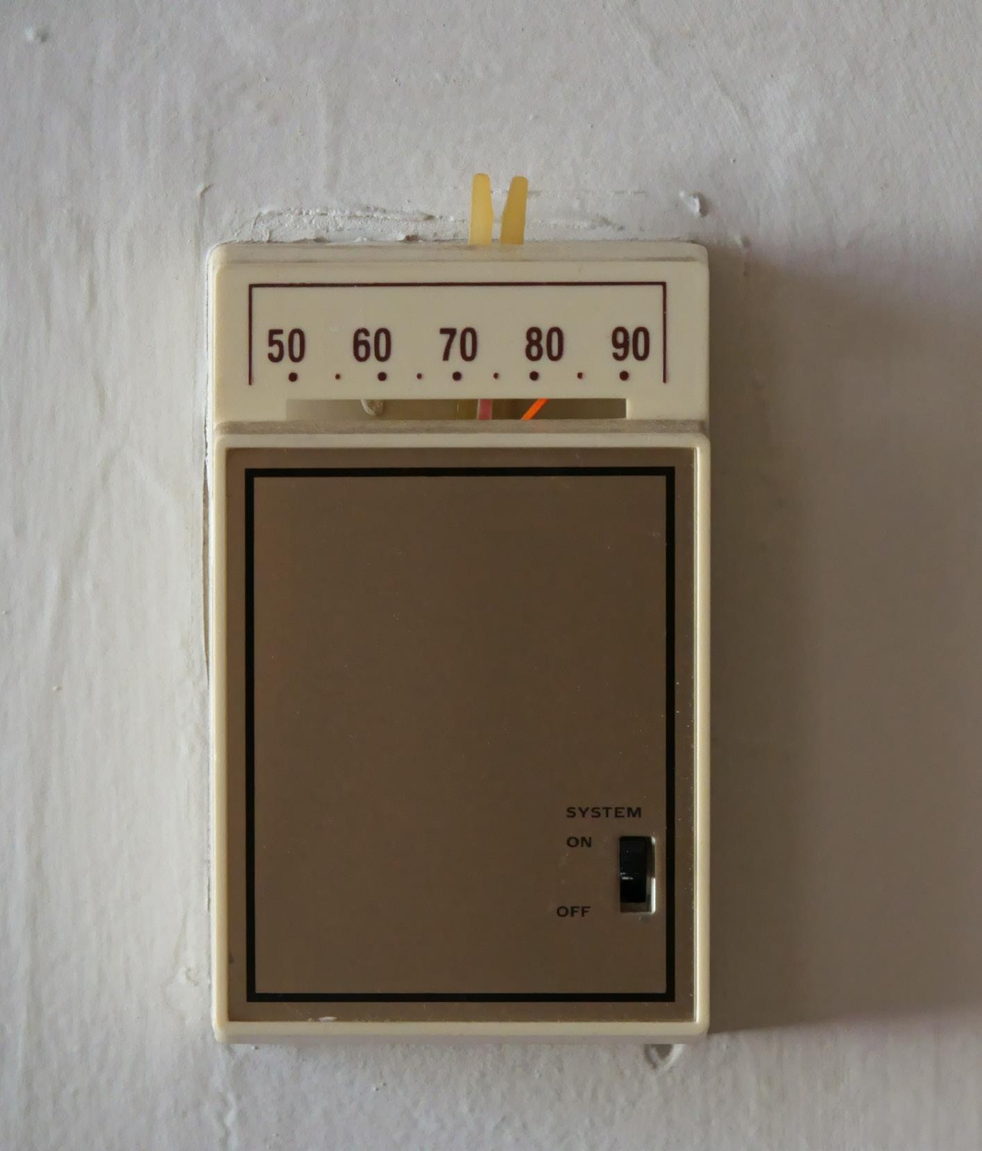
• Thermostats: typically, two mercury switches mounted on separate bi-metallic springs including a heat anticipator set to match the heating circuit amp draw. Thermostat location (then, as now) was important for proper cycling as was thermostat level … out of level meant imprecise control. The homeowner could adjust temperature settings using levers attached to the mercury switch mechanism.
• Fossil Fuel Kit: required to prevent a fossil fueled furnace and heat pump from operating in heating mode at the same time (except when defrosting).
• Outdoor Thermostat: required to set balance point switchover temp.
• Extra Power: fossil fuel kit and extra components such as time delay relays along with power needed to run the outdoor unit and furnace controls; typically, more than 70 va was necessary. Manufacturers recommended using one transformer rated higher than necessary (100 va in this case) because wiring in parallel a 40 va transformer fan relay along with the existing 20 va furnace transformer did not always provide enough power to ensure proper operation.
For these early generation heat pump systems, the typical heating strategy for units designed for the colder AHRI Region IV included a non-restricted mode and a restricted mode.
Non-Restricted Heat Pump Mode: in this strategy, the heat pump operated freely whenever the thermostat called for heat:
• First stage call: the outdoor unit starts on the “Y” cooling circuit. Since the reversing valve defaults to heating mode, they system initiates a heating cycle.
• Second stage call: the fossil fuel kit (FF Kit) interrupts the “Y” circuit and activates the furnace which runs until the second stage demand is satisfied.
• Time delay relay: installed in the FF kit, this relay prevents first stage from restarting immediately, thus allowing the furnace to cool down somewhat before the heat pump resumes operation should first stage still be calling. However, the non-restricted mode often failed in add-on systems installed in cold climates for a number of reasons:
• Below balance point the system would cycle endlessly between first and second stages.
• The cool down delay combined with the inability of first stage to provide adequate heating below balance point caused noticeable fluctuations in room temperature.
• Sometimes, the furnace alone satisfied both stages causing the heat pump to start the next cycle on first stage creating a staging delay that allowed room temperature to drop excessively before the furnace started again on second stage.
• These issues created homeowner complaints and service calls.
Non-restricted mode performed effectively when utilized with a matching electric air handler. Electric heat strips installed downstream of the indoor coil could operate along with the outdoor unit thus no fossil fuel kit was required.
Optional extra heat strips could be controlled using an outdoor thermostat, however, in a cold climate the heat strips would become the primary source of heating below balance point.
The other control option available at the time, Restricted Mode, used the FF Kit in combination with an outdoor thermostat designed to limit heat pump operation based on outdoor temperature.
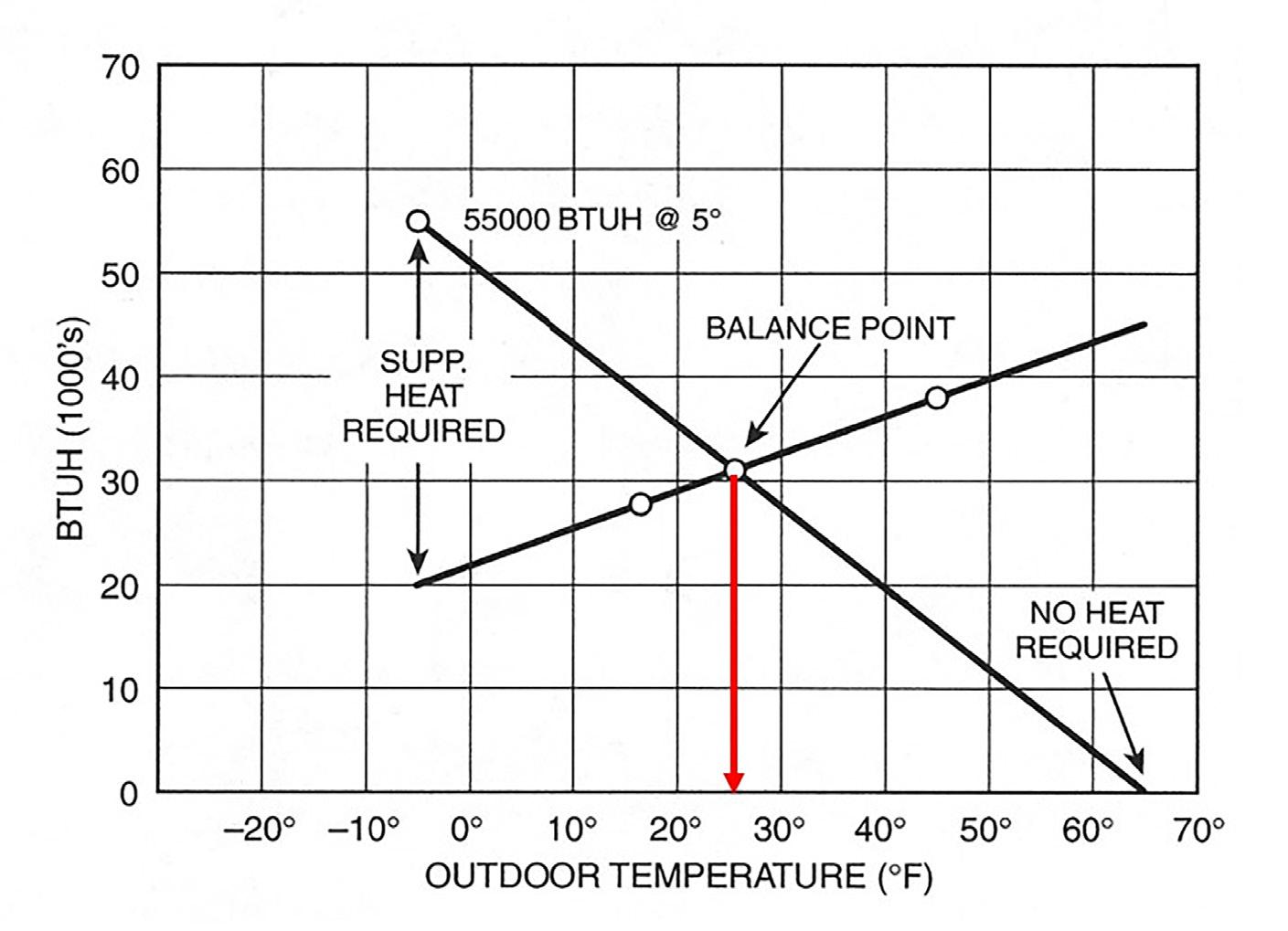
The heat pump runs only when the outdoor temperature is above a preset threshold. Below the balance point the fossil fuel furnace takes over 100% of the heating load. In Figure 1 you’ll see
Figure 1. Balance point graph
the balance point is 25F (-3.9C) based on a building heat loss of 55K Btu/h at -5F (-20.5C) and a heat pump that provides a maximum of 38K Btu/h at 47F.
The equipment slope demonstrates loss of heating capacity as the outdoor temperature drops.
The building slope shows the increasing heating requirement at lower temperatures. Where the two lines cross is the balance point.
In this restricted mode, the heat pump remains locked out until the outdoor temperature rises above the balance point plus a delta (typically 5 degrees F).
As an example, if the balance point is 25F (-3.9C), the outdoor unit remains off until the outdoor temperature reaches 30F (-1.1C).
Restricted mode only worked properly when the building’s heating load along with the heat pump’s performance curve were known and plotted as per Figure 1.
If the outdoor thermostat (ODT) was set too low (by guesswork), then the heat pump would run below balance point but fail to satisfy the thermostat.
Homeowners would notice the drop in room temperature, switch to the “emergency heat” setting that only allowed fossil fuel operation and then they would call for service.
If the ODT was set too high, then the furnace would take over prematurely even though the heat pump could still contribute. This setting wasted energy and increased operating costs; it’s like leaving money on the table.
Older control strategies relied heavily on mechanical logic and manual thermostat settings.
Perhaps this strategy worked well under ideal conditions, but I would argue such controls struggled to provide both efficiency and comfort, especially in cold climates.
MODERN HEAT PUMP CONTROL STRATEGIES
Today’s dual fuel control systems have evolved beyond the binary logic of fossil fuel kits and outdoor thermostats.
Dynamic feedback loops, real-time data and sensor networks help to optimize performance, efficiency and comfort. Control strategies typically rely on proprietary algorithms differing from manufacturer to manufacturer. One strategy I am personally familiar with uses Proportional and Integral error calculations to make decisions about how much capacity is needed at any given moment in time.
• Proportional Error (P) is the distance away from the room set point temperature as determined by the end-user.
• Integral Error (I) looks at the time away from the set point in real time.
• Thus, the algorithm uses P + I to deContinued on p8
cide how much capacity is required.
• P + I is displayed in the data as a load value, for example, a load value between 0 and 200 may be applied to a single stage conventional heat pump with one stage of electric heat back up. As the load value builds, the control will decide which unit to cycle and for how long. Once the load value of 200 has been reached in this example, the system will operate at full capacity.
• Additional algorithmic refinements such as duty cycle control, overshoot clamps, stage thresholds and stage inhibits all act together ensuring the system calls for heat or cooling only when necessary, and that the outdoor unit compressor and indoor fan runs at the correct speed to match the calculated load value command.
• System sensors monitor indoor temperature, outdoor temperature, coil temperature, humidity level, system refrigerant pressure, even occupancy sensors. The sensors feed data into the control algorithm so the control can determine the most efficient way to meet the heating or cooling load at any given time.
COLD CLIMATE HEAT PUMPS
Modern cold climate air source heat pumps often provide enough heat to satisfy the entire demand all by themselves in Canada’s banana belts. Whenever a cold climate heat pump cannot provide enough heat to satisfy the demand, then an add-on to fossil fuel or a hybrid system is specified.
Also known as Adaptive Intelligence, modern dual fuel controls have the advantage of providing precision load matching that reduces energy waste and prevents annoying room temperature swings for homeowners.
Hybrid controls provide smart fuel switching that saves energy costs by choosing the most cost-effective heat source. Adaptive intelligence avoids un -
“No control strategy can compensate for a poorly applied or improperly installed system.”
necessary cycling and staging.
For example, if the outdoor temperature is 20F (-6.7C) and the heat pump is keeping up with the load, the hybrid control will continue to use the heat pump, even though the legacy controller would have already switched to fossil fuel.
ADDED INTELLIGENCE
As systems continue to evolve, intelligent hybrid control will become even more refined.
I recently spoke with Tim Short of Lazlo Energy Services about the company’s innovative hybrid controller (soon to be in commercial production) that can be easily connected and configured to 24-volt hybrid systems.
According to Tim, “The Canadiandeveloped GreenBox (Figure 2) is a smart controller that optimizes heating in dualheated (hybrid) homes. It works with most existing thermostats, furnaces, and heat pumps, allowing homeowners to manage their systems to prioritize
lower utility costs, reduced emissions or a combination of both.
Installation is simple for contractors, who can also use the device’s performance monitoring and diagnostic data to better serve their customers.” For more information, visit getthegreenbox.ca.
ALWAYS FOLLOW BEST PRACTICES
While today’s cold climate heat pump systems boast impressive performance gains and sophisticated control technologies, the long-established principles of HVAC design and installation remain unchanged.
No control strategy can compensate for a poorly applied or improperly installed system. Thus, to ensure optimal performance:
• Specify the system correctly: choose equipment that matches the demands of the building and climate zone.
• Follow manufacturer guidelines and industry best practices during installation. Advanced new features like variable-speed fans and capacity modulation cannot rescue a fundamentally flawed setup.
• Commission every new installation to verify proper operation. Ideally, dispatch a qualified technician 24-hours post-installation to assess performance after the system has settled.
• Be sure to educate the end-user on proper operation and routine maintenance, as outlined in the owner’s manual.
Only by respecting these core principles can a hybrid heat pump system deliver the efficiency, comfort and reliability that today’s consumers expect. <>
Ian McTeer is an HVAC consultant with over 35 years of experience in the industry. He was most recently a field rep for Trane Canada DSO. McTeer is a refrigeration mechanic and Class 1 Gas technician. He can be reached at imcteer@outlook.com.
Figure 2. Canadian-based GreenBox Energy Technology is developing a hybrid heating smart controller.
Introducing Maelys. Cooling, without compromise.
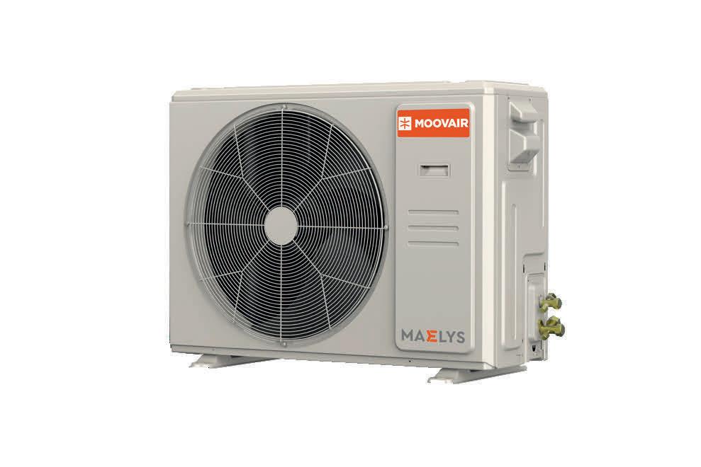
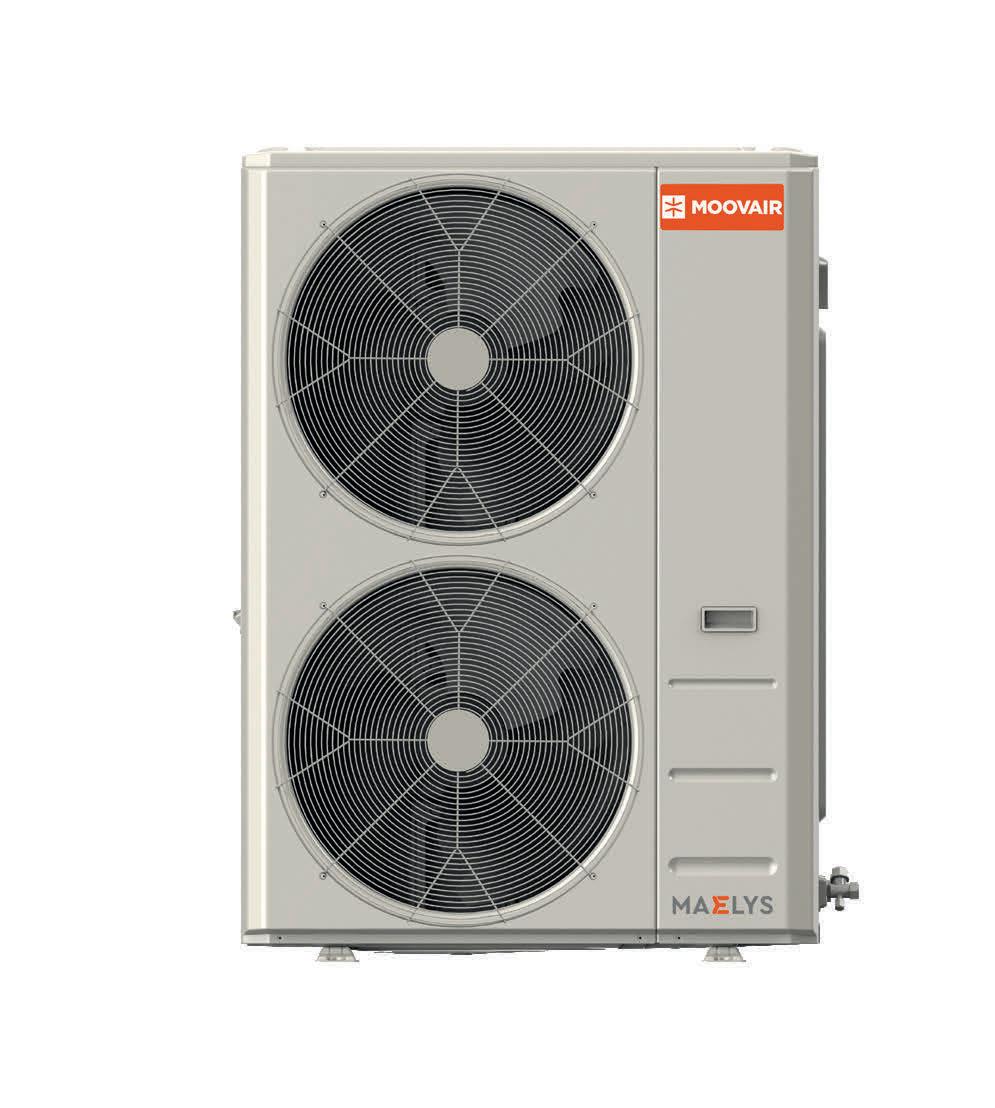
The new Moovair Maelys™ is a cooling-only, side-discharge unit designed for applications where air conditioning is the priority and traditional top-discharge AC units fall short.
New
Moovair Maelys™ CoolingOnly Side-Discharge Unit
• Cooling-only, Inverter-driven efficiency
• Compact, low-profile side-discharge design
• Fits tight spaces with flexible placement
• Quiet, comfort-first operation
• Up to 16.0 SEER2 / 11.2 EER2
• R454B low-GWP refrigerant
• Compatible with cased or uncased coils
• 10-year parts & compressor warranty
IMPROVING AIRFLOW
Correcting common errors on residential forced air HVAC systems based on the analysis of a home in the Victoria area.
BY TODD BACKUS, P.ENG.
I’ve worked in the HVAC industry for over 20 years in British Columbia and I see recurring issues with poor residential system design and installation. Cutting corners on heat loss and heat gain load calculations and a fundamental misunderstanding of proper HVAC system design are far too common in homes with ducted air handlers. With the growing transition to heat pumps for heating and cooling, as an industry we need to address system design basics.
One of the first items I inspect when trying to diagnose a poorly performing home is the return air system. A properly designed return air system balances airflows throughout the dwelling and ensures a more consistent and comfortable temperature for the occupants.
A lack of return air in the home creates pockets of still air that do not properly circulate with the rest of the building which decreases the effectiveness of the supply air system.
Forced air system airflow is measured in cubic feet per minute (CFM) using anemometers, and external static pressure (ESP) measured using manometers in inches of water column (“wc). In many cases, residential design assumes we’re going to lose 0.2” wc to 0.3” wc due to the whole ducting system. Consider that 0.2” wc is equal to only 0.007psi!
To minimize pressure loss, great care should be taken to move air through a duct using sweeping fittings and smooth
transitions. Many residential return air ducts are installed with the tops cut out of them, using wooden joists to transfer
air. Horrible fittings are accepted on the return air system that many contractors would never use on the supply side.
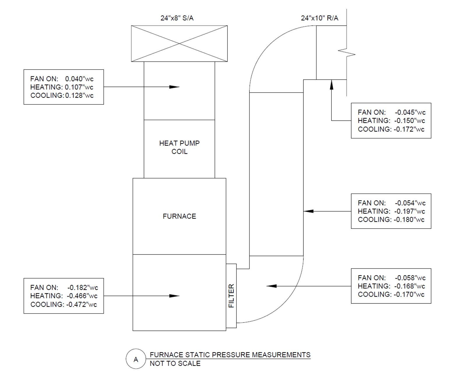
Figure 1. External static pressure measurements around an installed air handler.
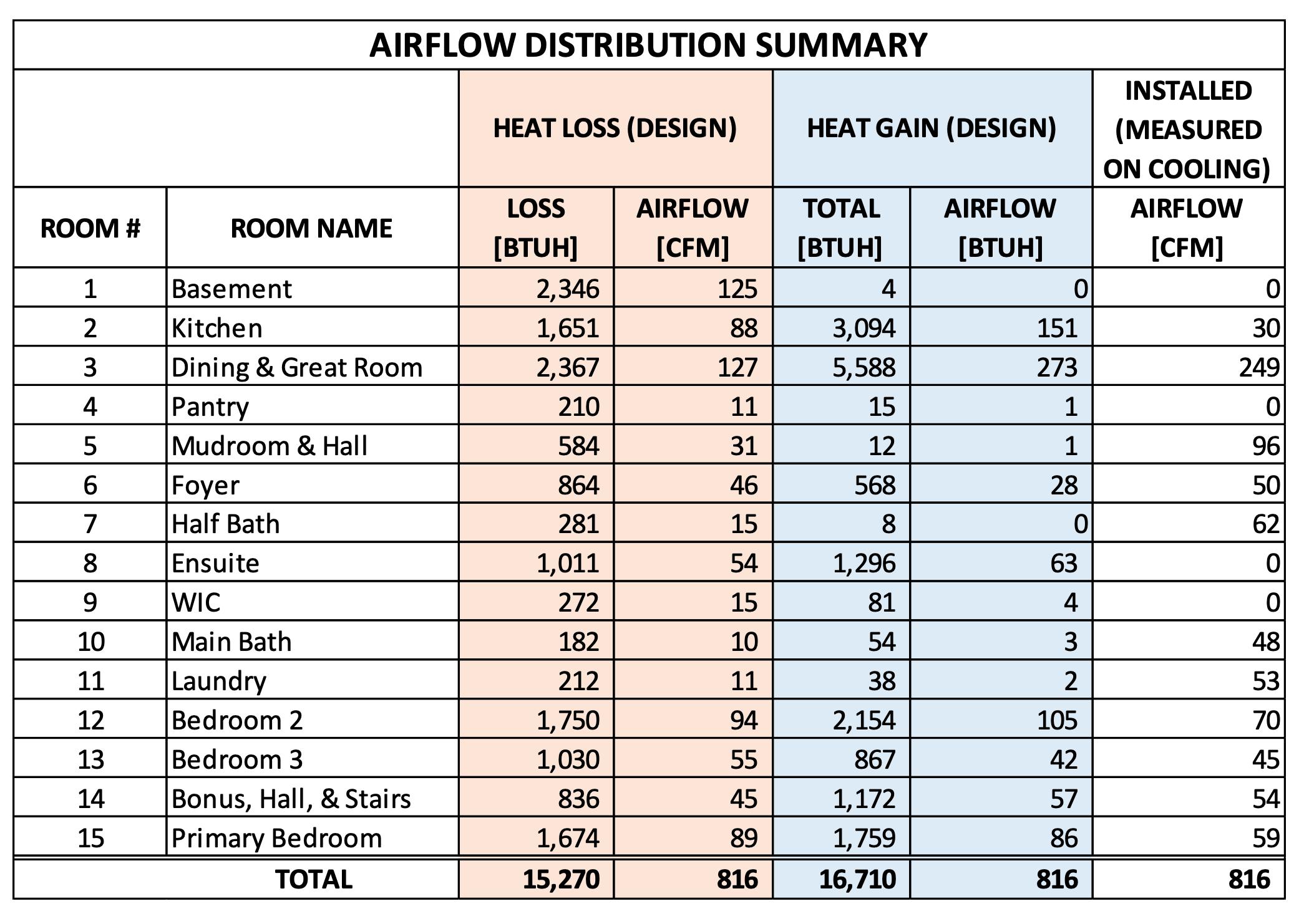
Figure 2. Heat loss/gain design load calculations and measured airflow at each register.
The image in Figure 1 shows a series of static pressure measurements I took while investigating a home in the greater Victoria region that was built in 2023. The deficiencies in its system created inconsistent temperatures throughout the house, resulting in poor thermal comfort for the homeowner.
The ducting is not sized to allow for any supply air dampers to be closed, which could have been used to balance the different airflow requirements for heating versus cooling seasons.
Figure 2 is a room-by-room table that includes my calculations for the heat loss and heat gain design loads, the measured airflow at each register, and the ideal airflow if it was distributed based on the load calculations.
The installed airflow rates that were measured are not consistent with the room-by-room heat loss and heat gain calculations. A CSA F280 load calculation is required by code (NBC/BCBC section 9.33.5.1.) on residential dwelling units. Many of the smaller rooms, located near the mechanical room, were over-supplied. The system would have functioned much better if that air was instead supplied to the kitchen and the upstairs bedrooms.
The HVAC designer tried to use a single exhaust grille from the HRV as return air
for the top floor, which is not allowed in the building code (NBC/BCBC 9.33.6.12. (2)). In some Part 3 commercial building applications using exhaust air to balance airflows is reasonable, especially when dealing with medical facilities. This approach fails in residential applications because the forced air system circulates way more air than the HRV—in this case 816 CFM versus 78 CFM.
This system is designed to supply 329 CFM to the top floor, but it only exhausts 78 CFM from the central bonus room. I prefer to exhaust from the bathrooms rather than a central living space because the bathrooms generally contain the lowest quality air in the dwelling.
The lack of air circulation on the top floor is particularly noticeable in the summer where heat stratification compounds the inconsistent temperature problems. The main floor is not balanced because it is returning nearly twice the air that is supplied to the main floor.
Adding ceiling fans on the top floor will help as a low cost, low impact, mitigation measure, but the real solution is to add a return air grille to the top floor.
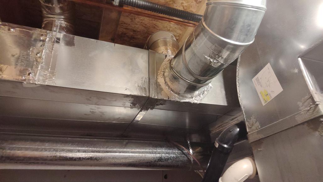
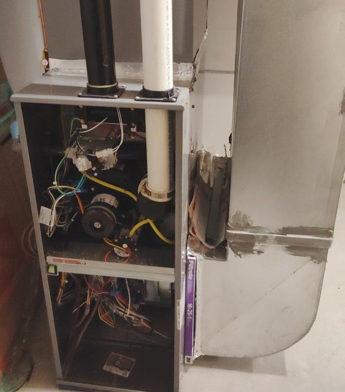
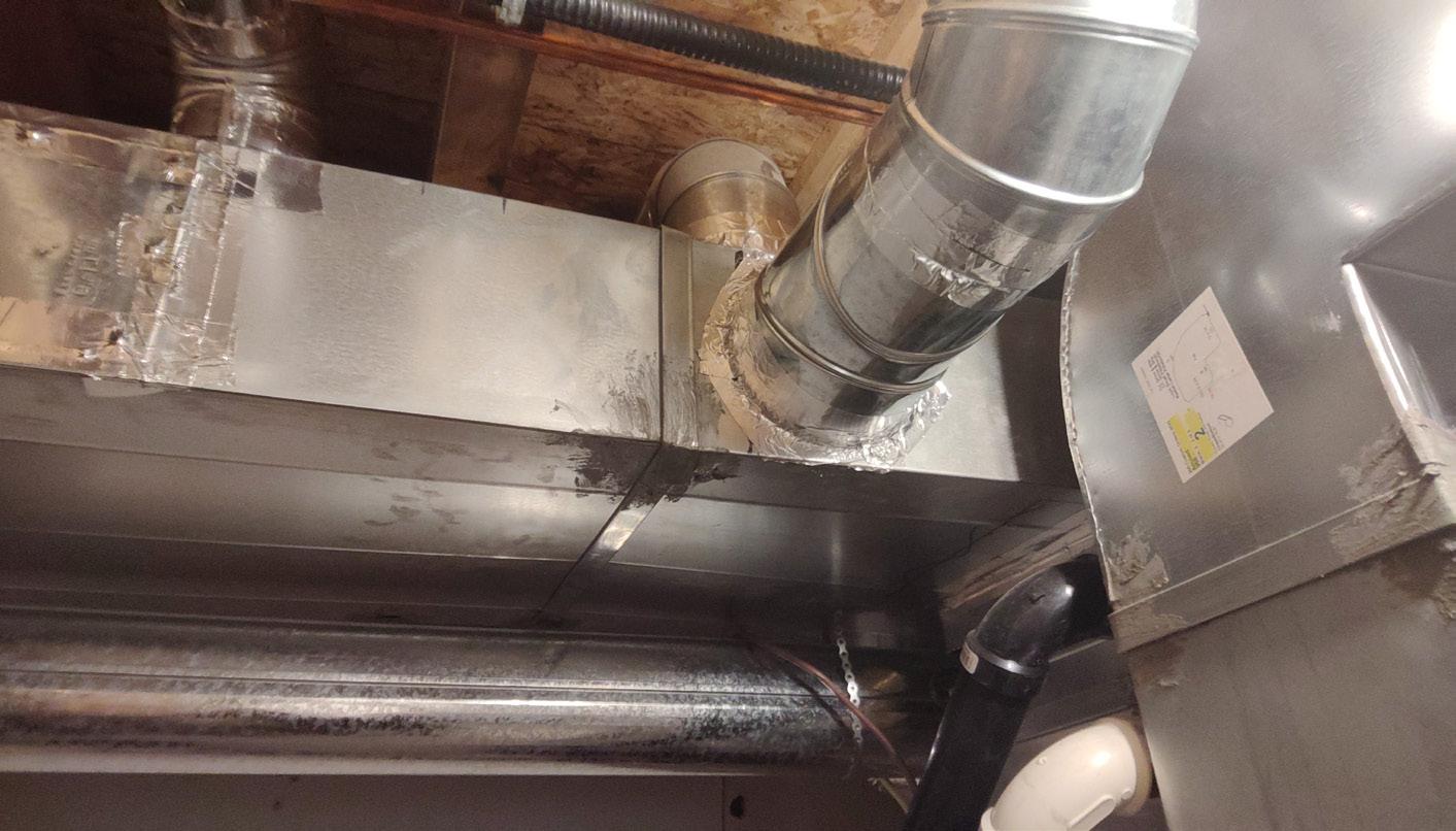
The sharp throats on the return air elbows and the 1-in. wide filter placed right at the fan inlet decrease performance (Image 1). No plenum take-offs were used, and the supply branch connec -
tions to the trunk were dove-tailed pieces of pipe (Image 2).
RECOMMENDATIONS
By my estimation, they could have increased the airflow rate of this system by 200 CFM with proper fitting selection and a 4-in. wide filter located farther away from the fan inlet.
The poor fitting selection, the lack of duct reducers on the mains, the dovetailed pipes into the trunk rather than side or top take-offs probably slipped under the radar in this system design because the home is reasonably small and well insulated.
In my opinion, it is the lack of return air on the top floor of a home like this that pushes the HVAC system over the line from being an under performer to a failed system. <>
Todd Backus, P.Eng., has been in HVAC since 2003, receiving a Red Seal Sheet Metal ticket in 2009 and then becoming an HVAC contractor/owner. Todd completed his Professional Engineer certification in 2023 and is currently Chief Operating Officer of TECA (Thermal Environmental Comfort Association). He can be reached at tbackus@teca.ca
Image 1. Placing the 1-in. filter right at the fan inlet and using square throat elbows decreases performance.
Image 2. Dove-tailed pieces of pipe connected to the supply branch where plenum take-offs would be preferred.
SWING SEASON SOLUTION
An air-to-water heat pump can satisfy a complete whole home or building comfort solution for all seasons.
BY JOHN SIEGENTHALER
Hydronically-heated concrete floor slabs can deliver silent, steady, and superior comfort. Their high thermal mass can dampen out reasonable variations in heat input to an extent that occupants are unaware that such variations even exist.
The same thermal mass can also deliver “full afterburner” heat output when cold outside air slides over the heated floor from an open door. That burst of heat output quickly restores comfort when that door is closed.
The concept that the floor slab can act as a thermal storage device to absorb heat from sources such as a heat pump running on low-cost off-peak rates is also an attractive quality, and one that has the potential to keep hydronic-based sys -
tems highly relevant as utilities plan how to meet future electrification goals.
So, what’s not to like about heated floor slabs?
Well, imagine this scenario: it’s a cool rainy day in early spring as a cold front moves through dropping the outdoor temperature to 7C/45F for a short time. The air is damp and the heated slab system has been turned off for the season.
The weather forecast is for sunshine and temperatures in the mid-20s to return the next day.
Should that floor slab heating system be turned on to chase the chill away for the next few hours?
IN FLOOR TIMING
Consider some Western Canadian locations where the overnight temperature in early spring and early fall drops to just above freezing, but “Chinook winds” and sunshine the following day bring the outdoor temperature into the upper 20s causing the building’s cooling system to kick in the following afternoon.
Should that slab heating system be turned on during that cool, but shortlived, overnight period, knowing that “summer like” conditions are only a few hours away?
Let’s assume the answer to this question is “Yes.”
The occupants, feeling slightly uncomfortable, flip the switch to start the system. If the water temperature supplied to the floor circuits is controlled based on outdoor reset control, the supply temperature might only be in the upper 70s F to mid80s F (20 to 30C) range when the outdoor temperature is 45 to 50F (7 to 10C).
Although those water temperatures are above the room temperature, the difference is small. It’s going to take several hours for the floor to make much improvement in comfort. By the time the floor warms the load could be eliminated by warmer outdoor temperatures, or by the internal heat gains from sunlight, people, etc.
If cooling is required by the afternoon,
any heat that continues to percolate from the floor surface just adds to the cooling load.
RAPID RESPONSE
Wouldn’t it be nice to have a system that can quickly warm the interior air, without waiting for hours as the floor slab slowly warms up?
Imagine a hydronic system with a “first gear” to quickly accelerate the space to some degree of comfort, as well as a “high gear” to keep that comfort cruising along during the dead of winter.
Consider the system shown in Figure 1.
This system uses a monobloc air-towater heat pump as its lead heat source. An electric boiler provides supplemental and backup heating when necessary.
Both heat sources supply a reverse indirect tank that serves as a buffer for supplying stable domestic hot water, as well as a hydraulic separating device for all four circulators in the system.
This tank can also buffer a small space heating load - to be described shortly. When the heat pump is first turned on in heating mode, the bypass zone valve (MV3) is open, and motorized ball valves (MV1) and (MV2) are closed. This allows the fluid to recirculate back through the heat pump until it reaches a temperature just above that in the upper portion of the buffer tank.
At that point (MV1) opens and the bypass valve closes. Heated fluid is delivered to the reverse indirect to maintain its temperature between 115 and 125F (46 and 52C).
A similar control scenario is used when the heat pump turns on in cooling mode. The bypass valve is open and both (MV1) and (MV2) are closed.
The fluid recirculates through the heat pump and quickly reaches a suitable temperature for cooling. At that point (MV2) opens, the bypass valve closes, and chilled fluid is delivered to the coil in the air handler.
Flow through the air handler’s coil is
provided by the same circulator (P1) that creates flow through the heat pump.
If the heat pump has a variable speed compressor its cooling capacity is regulated to maintain a pre-set supply temperature to the coil - typically in the range of 45 to 55F (7 to 12C).
MAKE ME WARM
There are two heating load circuits on the right side of the tank. One goes to the air handler, the other supplies the high thermal mass floor heating system.
Circulator (P3) provides a flow of warm fluid from the upper portion of the tank to the coil in the air handler. This is the “rapid response” heating method for those cool/damp shoulder season days. Ideally, (P3) is a variable-speed circulator that responds to the air temperature leaving the air handler. The faster the circulator runs, the warmer the leaving air temperature. Variable-speed “setpoint” circulators have been available on the market for several years, and they are ideal for this application.
After passing through the coil the cooler fluid returns to the lower portion of the indirect tank. Some or all of the flow leaving the coil might also go to the heat pump if it’s operating.
The high thermal mass floor heating system is also sourced from the upper portion of the tank. The supply temperature to the floor circuits is regulated by a motorized “injection” valve (IV), which is controlled based on outdoor reset. The greater the flow rate passing through the valve, the warmer the supply temperature to the floor circuits.
A simple two-stage temperature setpoint controller operates the air-to-water heat pump - or if necessary - the electric boiler, to maintain the upper portion of the tank between 115 and 125F (46 and 52C).
That temperature range is high enough to provide reasonable domestic hot water (DHW) delivery at 110F, and it’s also well within the operating range of modern air-to-water heat pumps, especially
those operating on R-32 or eventually on R-290 (propane).
LET ME BREATHE
Modern homes built to ever-tightening energy codes often require mechanical ventilation. The preferred method for exchanging stale air for fresh air is through a heat recovery ventilator (HRV).
Figure 1 shows an HRV tapped into the return side of the air handler. This ventilator draws air from the bathrooms, extracts up to 70% of the heat from that air, and transfers it to the incoming fresh air stream. That “conditioned” fresh air is then injected at the return side of the air handler.
A typical ventilation rate for a modest single-family home is 5 cubic feet per minute (CFM) per 100-square-feet of floor area. This equates to 125 CFM for a 2,500 sq. ft. house. That’s well below the air flow rate of 250-300 CFM per ton of cooling. A typical 3-ton rated air handler could be operated at 750-900 CFM to distribute the fresh air to all supply diffusers in the building, but doing so increases the power demand of the blower higher than necessary when only ventilation (and not cooling) is required.
Modern blowers with electronicallycommutated (EC) motors often have speed tappings allowing them to operate at lower flow rates in the range of what the HRV produces. This minimizes power input while distributing the fresh air through the same ducting system used for cooling.
A different motor speed tapping is activated to provide the higher air flow rates required for cooling.
ADDITIONAL FEATURE
Consider a situation in a cold northern climate where the outdoor temperature is -10F (-23C). If the HRV recovers 70% of the sensible heat from the outgoing 70F (21C) air, the incoming fresh air stream leaves the HRV at about 46F (7C). That’s still pretty cool to be introduced directly
into an occupied space.
This is where the variable speed setpoint circulator (P3) can provide additional functionality. It can operate to create a small flow rate of heated fluid through the air handler coil to boost the incoming 46F fresh air up to a neutral temperature in the range of 70 to 75F (21 to 24C) before that air is introduced into occupied spaces.
Since a monobloc heat pump is being used the entire system needs to operate with an antifreeze solution. This protects the heat pump during a power outage, or other situations when it remains off for several hours at sub-freezing outdoor temperatures. It also provides freeze protection for the air handler’s coil.
REMAINING RELEVANT
Consumers have lots of choices when it
comes to HVAC systems. Contemporary systems such as ductless mini-split heat pumps are incessantly pushed as being a “state-of-the-art” solution. In reality, these heat pumps provide forced air heating and cooling, but not domestic water heating and heat recovery ventilation. They’re a “partial” solution.
The system shown in Figure 1 provides that complete HVAC solution. It’s well suited to modern “electrified” homes, and it can be assembled from readily available components.
It’s a system that demonstrates that hydronics technology is not passé, but rather “cutting edge” in its versatility, energy efficiency, and its ability to deliver superior comfort.
It’s up to us — the North American hydronics industry — to keep hydronic-based systems relevant amidst all the marketing
efforts for competing HVAC options.
It’s up to us to educate homeowners, builders, architects, and energy consultants how a hydronic-based system, using multiple function air delivery subsystems, can provide complete solutions for HVAC using the latest heat pump technology.
Collectively we have the technology to provide superior and complete solutions for HVAC. Learn it, believe it, design it, and sell it. <>
John Siegenthaler, P.E., has over 40 years of experience designing modern hydronic heating systems and is the author of Modern Hydronic Heating (4th edition) and Heating with Renewable Energy (for more informationvisit hydronicpros.com).
Figure 1. A complete air-to-water heat pump HVAC solution suited to modern “electrified” homes and assembled from readily available parts.
ADVANCED HEAT PUMP TROUBLESHOOTING TIPS
A review of common areas of concern and new technologies to become familiar with.
BY DAVE DEMMA
Afew years ago, in a prior edition of HPAC, I explained the basics of how a heat pump operates, and I followed that up with another article on some first-level troubleshooting advice for heat pumps. That was almost three years ago now (check the archives online hpacmag.com), so it’s time for an update with some additional technical factors to consider.
To review, in the previous articles I laid out the principles of heat pump systems. In summary, the heat pump transfers heat from the conditioned space, but in a heat pump application the conditioned space is now outdoors. So, the evaporator is now located outdoors. The heat transferrs to the refrigerant in that process, plus the heat added to the refrigerant during the compression process is transferred to the air in the conditioned space via the condenser.
So, the heat pump is nothing more than the basic vapour compression cycle utilized in an air conditioning system, with added controls and valving (specifically the four-way reversing valve) to allow the system to either remove heat from the conditioned space (and transfer it to the outdoors) or remove (pump) heat from the outdoors (and transfer it to the conditioned space). As such, rather than a distinct evaporator and condenser, we now have two dual purpose coils, an “indoor” coil and an “outdoor” coil.
Like any mechanical system, the heat pump will experience periodic performance issues, some due to lack of maintenance and some due to mechanical/ electrical components failing.
Given that a heat pump is really an air conditioning system (which is providing cooling capacity to remove heat from the outdoor space), when troubleshooting a heat pump system which is under-performing the same basic methods used in air conditioning would apply. Some of those common concerns include:
• Voltage issues (low voltage, tripped breaker, blown fuses) .
• Thermostat issues.
• Plugged air filters or dirty indoor coil restricting the air.
• Four-way reversing valve not shifting to the heat mode.
• Four-way valve partially stuck in one mode or the other.
• Outdoor coil iced up.
In addition to these common issues, there are a few additional issues completely specific to heat pumps that might be experienced.
As mentioned above, the heat pump is a dual-purpose system with two modes of operation:
• Providing cooling capacity for the indoor space during periods of peak load.
• Providing cooling capacity for the outdoor space during periods of relatively low load.
As such, the system parameters and design conditions for each mode are drastically different. The system is normally selected to provide the required cooling capacity to maintain the mini -
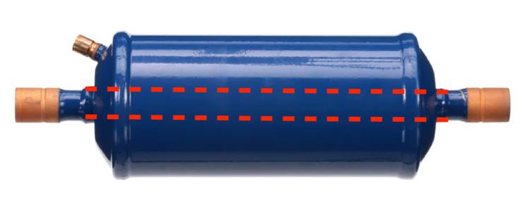
Figure 1. A charge compensator designed for heat pump applications, the Copeland ACC refrigerant charge compensator.
mum space temperature during the peak load conditions of the summer.
While important, the outdoor cooling capacity (providing indoor heating capacity during the colder months), is not the main parameter used in selecting heat pumps.
Due to the lower load requirement during the heating cycle, the refrigerant mass flow requirement will be less. In a system without a liquid receiver, this will result in the excess refrigerant (due to the reduced mass flow requirement) backing up in the condenser. This can result in higher discharge pressure. On the
NEW PODCAST SERIES FROM
surface this might seem ideal, as a higher discharge pressure would mean a higher discharge temperature, resulting in higher heat output. However, it must be remembered that the condenser’s function is to transfer heat from the superheated discharge vapour and facilitate the refrigerant undergoing a change of state from vapour to liquid. So, as the requirement for refrigerant mass flow reduces, and the expansion valve starts throttling closed, it is “liquid” refrigerant that begins backing up in the condenser.
Figure 2.
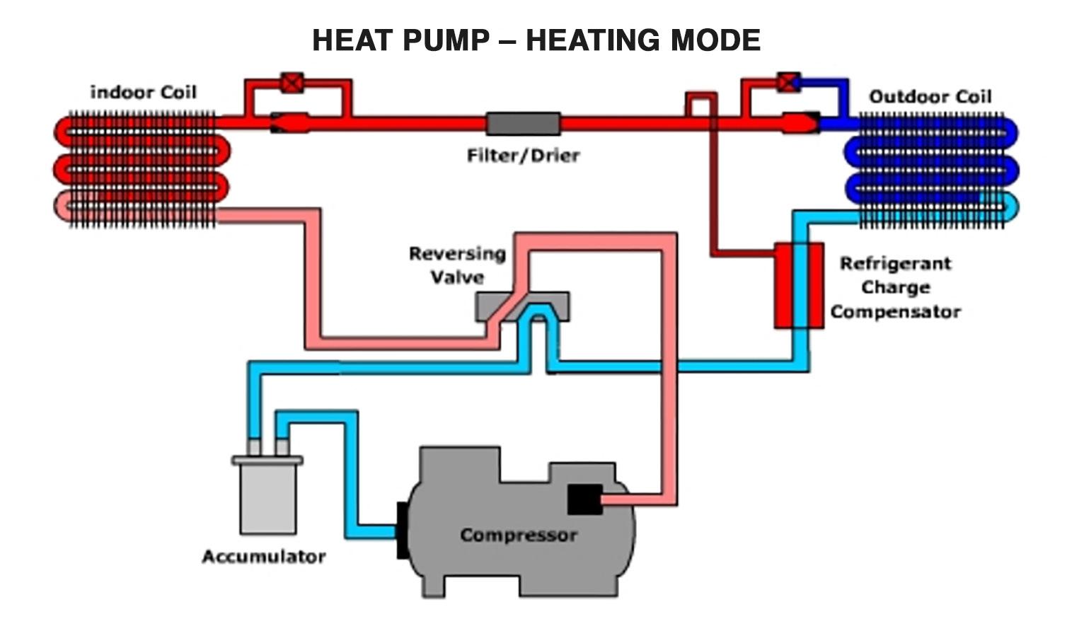
refrigerant charge compensator (RCC) during heating mode.
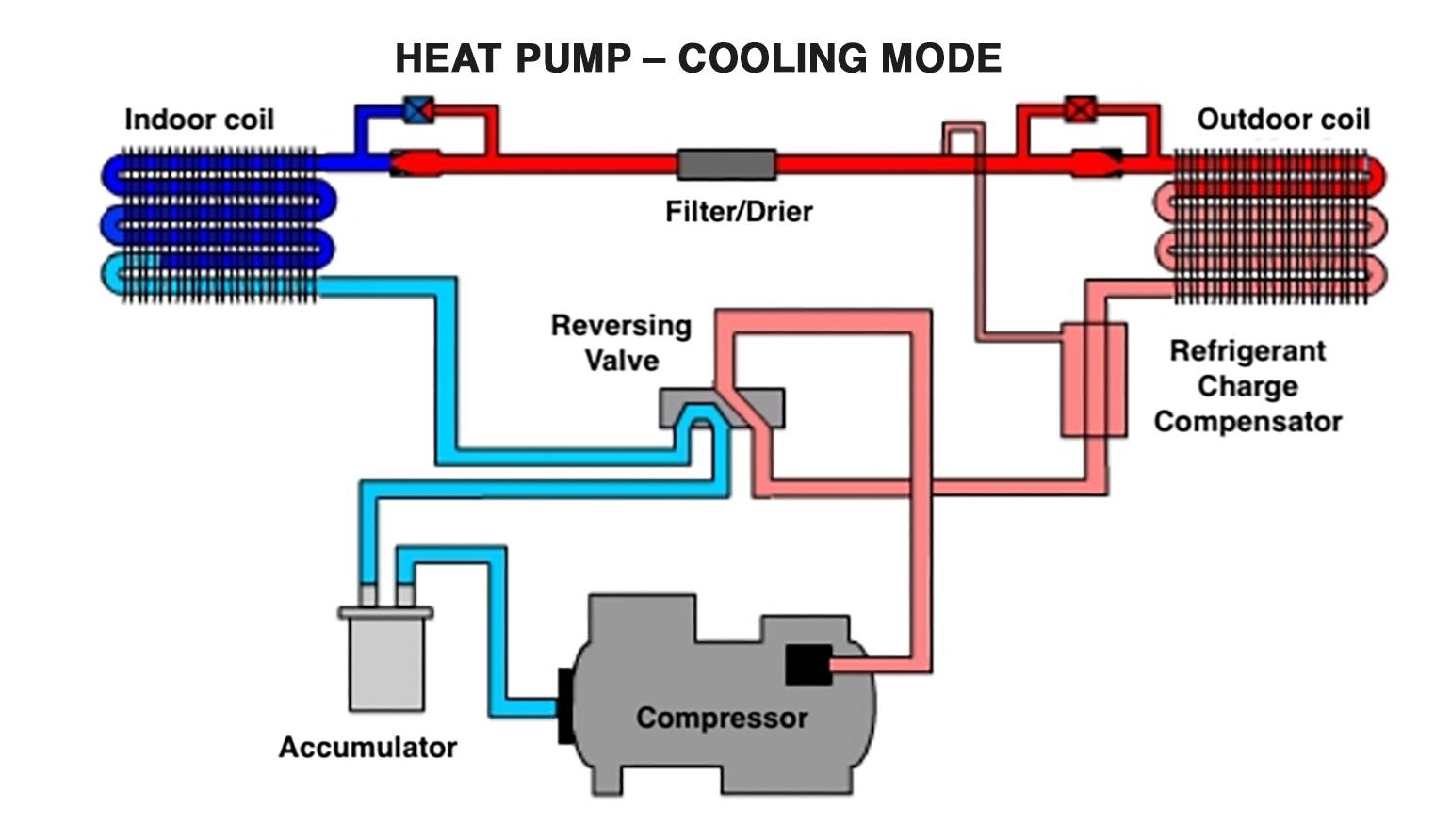
Figure 3. In cooling mode the temperature of the refrigerant flowing through the (RCC) will not attract excess refrigerant in the system.
As this begins happening, it results in a reduction in the useful condenser surface area necessary to transfer heat from the superheated discharge vapour to the air in the conditioned space, which translates to a reduction in heating capacity.
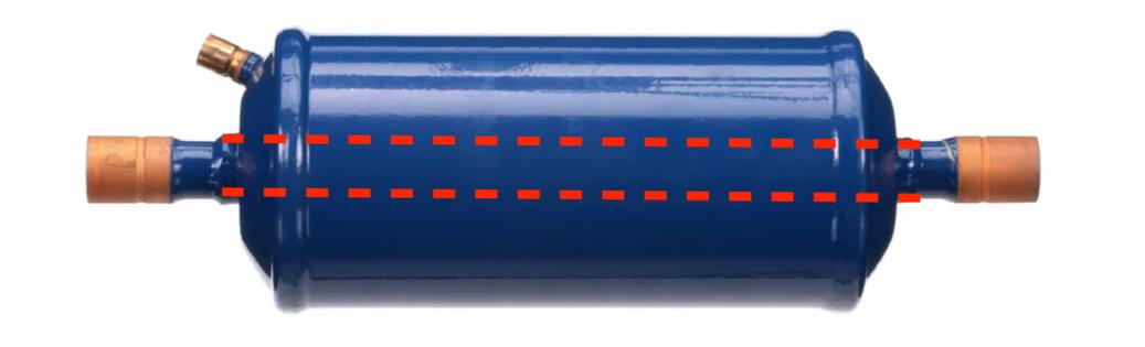
An added component in the system to nullify this condition is a “Refrigerant Charge Compensator (RCC)”. Its function is to divert the excess refrigerant charge from the system during the heating mode and temporarily store it in the RCC.
While the appearance of this component is similar to that of a suction filterdrier (see Figure 1, page 16), internally it is quite different. The dotted red lines illustrate the vapour flowing though the shell in a straight piping run, which prevents any suction vapour from accumulating inside the shell. There is a single liquid connection, which allows liquid to enter the shell when it isn’t required during periods of reduced mass flow in the heating mode.
The diagram in Figure 2 (page 17) is a system schematic showing the refrigerant flow during the heating mode. The RCC is located near the outlet of the evaporator (outdoor coil), with the liquid connection coming from the inlet of the evaporator (outdoor coil).
The excess liquid refrigerant will be at-
tracted to flow towards the coolest temperature. The cool suction line running through the shell provides this cooler temperature, with the excess liquid refrigerant flowing to the internal volume of the RCC.
To prevent too much liquid refrigerant from migrating to the RCC, these components must be sized according to the system capacity and estimated excessive refrigerant charge
The refrigerant flow during the cooling mode will see the RCC located near the outlet of the condenser (outdoor coil), with the liquid connection coming from the inlet of the condenser (outdoor coil). Liquid refrigerant will not be attracted to flow into the RCC, as it is now discharge vapour flowing through the inside if the RCC (see figure 3, page 17).
ADVANCEMENTS IN TECHNOLOGY
Again, one of the deficiencies in heat pump applications is the somewhat limited heating capacity available. A relatively new technology is starting to appear in heat pump equipment to addresses this issue, and provide additional heating capacity.
Copeland has been manufacturing vapour injection scroll compressors for some time now and there are now many
on the market. These compressors have a secondary suction port which allows vapour to enter the scroll set at some intermediate position (and corresponding intermediate suction pressure). This provides cooling capacity for a liquid subcooler (sometimes referred to as a system economizer). As applied on heat pumps, it will provide a dual purpose. The subcooled liquid results in increased system performance. More importantly, during the lower load condition during the heating mode, it provides additional load for the compressor, which results in an increased amount of heat content in the discharge vapour, so more heating capacity in colder temperatures.
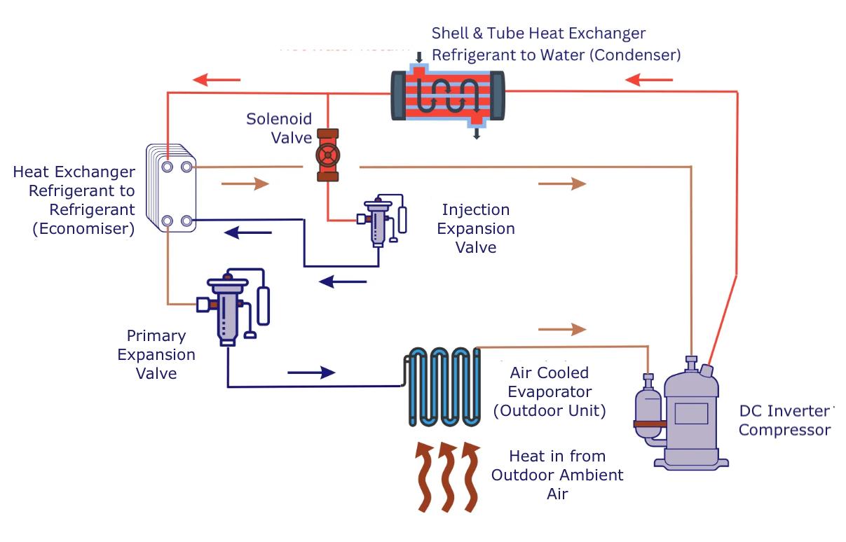
The schematic in Figure 4 shows the flow of an air-to-water heat pump system with a vapour injection compressor providing capacity for the subcooling circuit.
Another advancement in technology has heat pumps using variable speed compressors. They are powered by direct current (DC) inverters, and this allows the compressor to operate continuously, matching the compressor capacity (speed) to the required capacity at any given moment.
The compressor speed is modulated using a variable speed drive. As the compressor speed is modulated, there will be a corresponding modulation in the refrigerant mass flow and compressor capacity. Rather than the conventional heat pump, operating at two speeds (100% or 0%), new systems can operate anywhere from 15%/25% to 100%, better matching the required capacity during varying conditions.
Advancements in technology are great, right! <>
Dave Demma holds a degree in refrigeration engineering and worked as a journeyman technician before moving into the manufacturing sector where he regularly trains contractor/engineering groups. Contact Dave at ddemma@uri.com.
Figure 4. Vapour injection compressor technology in an air-to-water heat pump system.