Decarbonizing Buildings Economically p. 11
2026 Industry Survey Results p. 14
Ensuring Safe Access for High-rise Maintenance p. 22 Spring 2026
ccemag.com
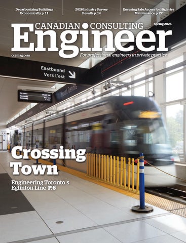
Crossing Town Engineering Toronto’s Eglinton Line P.6
Decarbonizing Buildings Economically p. 11
2026 Industry Survey Results p. 14
Ensuring Safe Access for High-rise Maintenance p. 22 Spring 2026
ccemag.com
Crossing Town Engineering Toronto’s Eglinton Line P.6