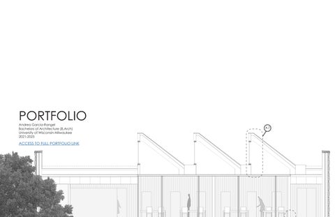
PORTFOLIO Andrea Garcia-Rangel Bachelors of Architecture (B.Arch) University of Wisconsin-Milwaukee 2021-2025
ACCESS TO FULL PORTFOLIO LINK
01 Milwaukee Rare Book Archive 2024 Comprehensive Design Studio Location|Milwaukee Programs|Rhino, AutoCAD, Lumion, Photoshop, Illustrator
The Milwaukee City Archive project fosters community engagement and accessibility. Adjacent to City Hall, it serves as a cultural and educational hub, offering access to historical books, manuscripts, and photographs. A gallery space and an independent coffee shop further enrich its inviting public atmosphere. Seamlessly integrating functionality, sustainability, and aesthetics within its urban surroundings. The exterior facades are cladded in grantique stone placed in a brick pattern, complementing neighboring buildings while standing out with its darker tone. Ultimately, this project embodies the philosophy that simplicity and functionality create lasting beauty, establishing an enduring and resource efficient landmark for the community.
Given the steady foot traffic in this part of the city, from nearby offices and casual strollers, the space was designed to act as a natural gathering point. During the early design phases, the focus was on creating a welcoming entrance that would draw people in, whether or not they were visiting the archive. The intent was to encourage passersby to stop, enjoy the seating areas, or grab a coffee, making it accessible from both the north side of the building and from within the archive itself.
Exploded Axonometric Diagram Sawtooth Roof System
Steel Structural System Radiant Flooring
The archive is constructed with a steel frame structure and concrete floor slabs embedded with radiant heating coils. The exterior is clad in Krukowski dark Aqua Grantique, cut into narrow pieces and laid in a brick-like pattern.
Structural Glass Flooring
Krukowski Grantique Stone
Wood Wall Paneling
Rendering #1 Interior rendering of the thirdfloor reading room, defined by a sawtooth roof that brings in natural light and doubles as a light well for the building. A glass floor visually connects the space to the lobby below, while warm wood paneling softens the materiality and creates an inviting atmosphere
Floor Plans
A
N
Ground Plan + Site Plan Scale:1/8”=1’
A
Second Floor Plan Scale: 1/8”=1’
Third Floor Plan Scale: 1/8”=1’
Exploded Section Drawing Axonometric Diagram
Construction Details 1 2 3 4
Roof and Skylight Detail A.7 Scale: 1 1/2”= 1’
Corner Detail
Interior Finish
5 6
1.Metal Roofing
Steel Stud Wall
7 8
Air,Water,Vapor Barrier
9
2.Underlayment 3. 3/8” Sheating
Smart CI Clips
4.6” Insulation
6” Insulation
5.Vapor Control
10 11
Air Cavity
12
6.Steel Decking
13 14
7.Steel I Beam
15
3-1/2” Gneiss Stone
8.Interior Finish 9.Wood Blocking 10.Sealant and Backer Rods 11.Flashing 12.FreMarq Mullion 13.Surface 1: Anti Bird Collision Coating 14.Surface2: Low E-Coating 15.Surface 3: Frit Pattern for Solar Gain Reduction 16.Steel Angle 17.Clip Angle 18.Mechanical
1 2 4 5 6
9
4 8
Glass Floor A.8 Scale: 1 1/2”= 1’ 1.4.5” Glass Floor 2.Space Membe4 3.Silicone Cushion 4.Perimeter Member
7
5. Decking
16 17 16
6.I Beam
1 2 3
7.Steel Angle 3
8.Clip Angle
5
4
18
6 7 8
7
Exploded Exp Rendering ploded Axonometric A#2 xonometric D Diagram iagram Archive features a two-story atrium functioning as the main lobby and central gathering space, creating visual and spatial connections to the second-floor offices above.
Rendering #3 Café corner and outdoor lounge serving as a social hub for pedestrians, connecting the archive to the surrounding streetscape through greenery and accessible seating.
02 By-Passing Skin 2023 Building Construction Location|Milwaukee Programs|AutoCAD, Rhino, llustrator
Detail A
Detail B
Detail C
The project seen here involves designing a typical bay of a glass clad steel frame for a reading room on a small college campus facing a river. This south facade will feature a 1” insulating glass that provides a view to the river while managing solar gain and glare. The adjacent west wall is a 20” masonry wall. The section drawing incorporates a mechanical strategy to prevent down drafting off the glass and addresses heating, cooling, and ventilation for the reading area. The design will utilize a singular vertical aluminum element, specifically Kawneer’s 1600 wall system mullion “162-002” , with a wind design loading 30 PSF for double twin span.
Elevation 3/8”=1’
Section 3/8”=1’
Here we see this illustrated in a typical bay elevation, a wall section, and a plan section all scaled at 3/8”=1’. On the following page there are three details highlighting different parts of the section drawing, all drawn at 1 1/2”=1’. Plan 3/8”=1’
Black Silicone Adhesive Kawneer's 1600 Wall System 1 Mullion "162-002"
Detail A 1 1/2"=1'
Sealant and Backer Rod Insulation
HVAC Vent
Floor Slabs W/Radiant Heating/Cooling Concrete Slab
Flashing
Insulation
Green Roof
Kawneer's 1600 Wall System 1 Mullion "162-002" CW Slip Connection
Desiccant Beads
3 21 " Steel Decking
Concrete Footing HVAC Duct
18" Deep Steel I Beam
Wood Blocking
Detail C 1 1/2"=1' 3" Rigid Insulation
Surface 1: Anti Bird Collision Glass Coating
Surface 3: frit pattern on glass for solar gain reduction
Celvis
Anchoring
Surface 2: Low E-Coating
Detail B 1 1/2"=1'
03 Mass Timber Structure with Metal Rainscreen Cladding
2023 Building Construction Location|Milwaukee Programs|AutoCAD, Rhino, llustrator Detail A
This project investigates the design and technical performance of an infill-frame wall system, using a laminated mass timber structural frame combined with a metal rainscreen cladding. The goal of the exercise is to clearly articulate the relationship between structure and enclosure, emphasizing how the exterior expresses the underlying timber frame while maintaining a high performance building envelope. Sustainability is central to the project, prioritizing low–fossil fuel operation and material choices that minimize negative environmental impacts. The design focuses on the south-facing corner of a two-story faculty office building on a small college campus. The façade is cladded in metal panels attached to the exterior of the mass timber frame, with openings sized to provide daylight and views for 16’-wide shared offices while limiting glazing to 35–45% of the elevation. Presentation materials consist of a typical bay elevation, wall section, and plan section at 3/8” or 1/2” = 1’-0”, along with three fully annotated large-scale construction details at 1 1/2” = 1’-0”.
Detail B
South Elevation 3 8"=1' Detail C
Section 3 8"=1'
Plan 3 8"=1'
Standing Seam Zinc Metal Panel
Walker AviProtek glass(bird safe glass)
live grass engineered soil waterproofing membrane bonding adhesive
Metal flashing
cross laminated timber metal coping
Backer rod
insulation insulation adhesive
6" mineral wool insulation
and sealant
cross laminated timber
air/water/vapor barrier
Vertical Rail
concrete
pressure equalized cavity
Glulam Beam
air/water/vapor barrier
Rainscreen metal bracket
cross laminated timber
6" rigid insulation
anti-bird collision glass coating
sun shade
Detail A 1 1/2"=1'
3" Floor topping
Rigid insulation
Rainscreen metal bracket Standing Seam Zinc Metal Panel
cross laminated timber Glulam Beam
Vertical Rail
Detail C 1 1/2"=1'
pressure equalized cavity
Corner L shaped steel plate
Detail B 1 1/2"=1'
04 Punched Masonry Corner Study 2023 Building Construction Location|Milwaukee Programs|AutoCAD, Rhino, llustrator
This project explores the structural and spatial implications of loadbearing masonry through the design of a two-story faculty office building corner. The exercise focuses on expressing the inherent character of a “punched wall” while integrating sustainable strategies that minimize fossil-fuel dependence and prioritize alternative healthy materials. The south-facing wall is constructed with 8” concrete masonry units supporting 8” precast concrete planks at the floors and roof, with a modular brick veneer forming the exterior finish. Each 16’-wide shared office requires ample daylight and views, prompting the careful design of window openings within the loadbearing façade. Design attention is given to three critical conditions: the way the masonry meets the ground, the expression of the wall as a structural loadbearing element, and the detailing of larger punched openings. Here we see this illustrated in a typical bay elevation, wall and plan sections, and two large-scale construction details, all drafted at architectural scales to clearly document the assembly and design intent.
South Elevation 3/8”=1’
Plan 3/8”=1’
Section 3/8”=1’
wood block vent
metal cap
engineered soil waterproofing membrane bonding adhesiveinsulation insulation adhesive
bond beam
1" air cavity
brick masonry
air cavity precast plank
3" mineral wool insulation
live grass
CMU mortar net vent
interior finish
furring strip
precast plank
3" Mineral Wool Insulation Concrete Topping
insulation
Footing CMU mortar net bond beam sun shade
window
Foundation Detail 1 1/2”=1’
Andrea Garcia-Rangel
Excercise#1
10/05/2023
Sheet #2
Wall Detail 1 1/2”=1’