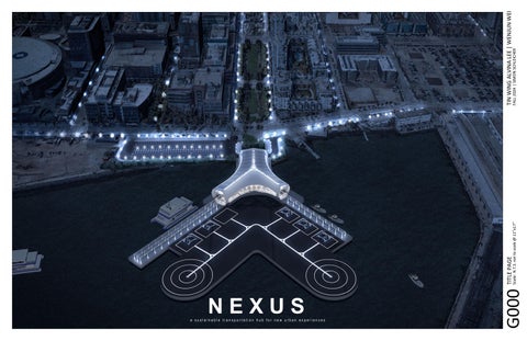
Alvina Lee & Wenjun Wei - Integrated Studio

Page 1


Located in San Francisco, our transportation hub is an integration of the ferry terminal and eVTOL vertiport. The design features three distinct branches that define the surrounding into three zones - the eVTOL vertiport, large and small ferry landings. The main branch also serves as a corridor that extends from the existing green belt, it is an inviting interior green space illuminated by skylights. The corridor also has an unobstructed view of the vertiport and sea. At the intersection of these three branches, we created a vibrant waiting area with café and gathering spaces. As for the second floor, it accommodates administrative and co-working spaces. This project aims to foster urban mobility and create a lively destination within San Francisco's waterfront.

OCCUPANCY (CLASSIFICATIONS & CALCULATIONS)

PROJECT TITLE

Salesforce Transit Center

1400000 sqf.

The Salesforce Transit Center serves as a pivotal example of transportation acility design, the building has a clear sectional organization where different modes of transit are thoughtfully arranged across levels. We took inspiration from the design approach, yet through a horizontal rather than vertical organization. We have developed three brances, each dedicated to a specific mode of transport, showing functional clarity. While Salesforce Transit Center incorporates a striking atrium with skylight as a celebrated space, our design emphasizes the plan's intersection of the three branches, we offered an unobstructed view of the green corridor and drone landing pad. We also aim to incorporate accessible green space for the public, like the green roof design of Salesforce Transit Center.

Cross section of Salesforce Transit Center demonstrates spatial clarity in terms of sectional program organization, each mode of transportation has a distinct level.

Passenger waiting area along with a loop bus circulation connecting to the bus ramp

Entrance hall, street level bus plaza and retail spaces

CONCOURSE]

Train ticketing, retail and bike storage

[TRAIN PLATFORM]

3 train platforms for 6 CalTrain tracks

[LOWER
[BUS DECK LEVEL]
[ROOFTOP]
[GROUND LEVEL]
Pelli Clarke & Partners
Rooftop park with garden, seatings and green spaces

[EXTENDING THE GREEN CORRIDOR]

Enhances the existing green corridor by having the main branch of the massing as an interior green space. The double-story corridor is topped by a skylight, the vibrant growing space foster connection between exterior and interior.

[eVTOL TAKE-OFF AND LANDING PATH]

To ensure safe operations, the terminal building and the vertiport was oriented

to optimize the landing and take-off path of the eVTOL. The path was oriented

to avoid crashing into the terminal and travelling across residential areas.

[PEDESTRIAN CIRCULATION ON SITE]

By extending established route through the terminal's canopy, a seamless pedestrian transition was created. The terminal design enhances accessibility, also encourages connection with the surrounding public spaces and circulation.

ITERATION 1

same width for all three branches

ITERATION 2

varying width for all three branches

ITERATION 3

widening the main entrance branch

ITERATION 4

narrowing the main entrance branch varying lengths for all three branches

ITERATION 5

narrowing the intersection space

ITERATION 6

double layering the side branches

ITERATION 7

slanted walls for the facade

ITERATION 8

reducing the radius of the front curved facade

EFGH D C B A

SCALE: 1/8" = 1'

SCALE: 1/8" = 1'

Tensile facade is used at the major opening to provide an unobstructed view at the major facade of the building

[OPERABLE SKYLIGHT]

5520 sqf. total

A rainscreen facade is used to prevent water from infiltrating the building structure

[RAINSCREEN CLADDING FACADE]
[TENSILE CABLE GLASS FACADE] [COVERED WALKWAY]
[PV PANELS]

[Cladding Panel]

[Air Cavity]

Section Gutter]

Skylight]

[Top Flashing]

[Rigid Insulation]

[Box Section Gutter]

[Cladding Panel]

Cavity]

Barrier]

Insulation]

[Laminated Glass]

[Tension Cable] [Box Section Gutter]

Plate]

[Facade Louvre] [Drainage Channel]

Channel]

[ENVIRONMENTAL MEASURES]

Natural lighting and ventilation were both considered when designing the massing and elevation. A long strip of operable skylight is included in the design, this allows sufficient natural daylighting throughout the day, the results could be seen from the simulation results of daylight factor. As for ventilation, the operable skylight facilitates stack ventilation, as for openings facing the vertiport allow cross ventilation. Considering the large amount of sunlight throughout the year at the site, blinds and overhang are also included in the design.

DAYLIGHTING]

[NATURAL DAYLIGHTING]

[WESTERNLOWANGLESUN]

WIND]

VENTILATION]

[FLOOR TEMPERATURE CONTROL]
[NATURAL
[PV PANELS] [STACK VENTILATION]
[HEATPUMP]

[Site Climate Analysis - San Francisco]

San Francisco enjoys predominantly mild temperatures, rarely dropping below 3°C or exceeding 30°C, with averages ranging from 12°C to 18°C throughout the year. This stable climate aligns with the city's reputation for comfortable weather. The wind rose diagram indicates consistent westerly winds, primarily from the west and west-northwest, which play a crucial role in shaping the local climate by bringing cool, moist air from the Pacific Ocean.

Classified as ASHRAE Climate Zone 3C (Warm-Marine) by the U.S. Department of Energy, San Francisco experiences mild temperatures, high humidity, and minimal demand for heating or cooling.

[Wind rose & Sun path diagram]

The site conditions significantly influence the building's orientation. With prevailing winds primarily from the west and northwest, the corridor was aligned along the wind direction to enhance natural cross-ventilation. Additionally, the sunpath diagram guided the design to minimize glazing on the south façade, reducing the risk of overheating and optimizing thermal comfort.

[FIRST FLOOR DAYLIGHT FACTOR]

The daylight factor (DF) on the ground floor fluctuates within a 5% range for both the median and mean values, indicating an optimal lighting condition for the waiting hall. Higher DF values are observed at the three ends of the building, attributed to the fully glazed facades at these locations.

[SECOND FLOOR DAYLIGHT FACTOR]

The daylight factor (DF) on the second floor is even more favorable, maintaining a value close to 5% without excessively high variations throughout the space, ensuring balanced and consistent lighting.

[LONG

SECTION DAYLIGHT FACTOR]

Examining the daylight factor results alongside the long section, the skylight along the central axis effectively delivers ample daylight to the double-height waiting hall. While some areas near the middle may be slightly underlit due to their distance from the side glazing walls, the majority of the space is well-illuminated, ensuring sufficient natural light throughout.

[SHORT SECTION DAYLIGHT FACTOR]

The daylight factor analysis in the short section highlights the need for artificial lighting in the ground floor supporting rooms located along the sides. However, both the corridor and offices on the second floor are well-illuminated by natural light, reducing the reliance on artificial lighting in these spaces.

GREENERY CORRIDOR & WAITING HALL

[FIRST FLOOR DAYLIGHT AVAILABILITY]

Daylight availability on the ground floor does not achieve 100% coverage, as certain functional rooms, such as the WC and DOAS room, do not require windows and depend on artificial lighting. However, the central greenery corridor is fully illuminated by natural light, supported by the design of the eastern glass wall and the skylight integrated into the roof. Additionally, the shop and restaurant will feature glazing along the corridor side to allow natural light to enter.

[SECOND FLOOR DAYLIGHT AVAILABILITY]

Daylight availability on the second floor is nearly 100%, as all meeting rooms and offices are equipped with additional skylights along the sides, providing abundant natural light. To mitigate glare within the rooms, semi-transparent materials, such as Kalwall, will be considered for the skylight glazing to minimize excessive direct sunlight.

[sDG Annual Glare]

The annual solar glare is relatively high due to the unprotected skylight and the fully glazed facades on the east and west sides. However, the central corridor, abundant with greenery that thrives on sunlight, benefits from direct sunlight in this area. Given that the central corridor serves as a waiting area, solar glare is not a significant concern in this space.

[Annual

Solar Exposure]

The annual solar exposure aligns with the findings on solar glare. To mitigate glare and excessive solar radiation, shading devices such as louvers can be implemented, or the glazing can be upgraded to low-emissivity (low-e) glass to reduce heat and light penetration while maintaining adequate natural lighting.

[STEEL FRAME STRUCTURE & CONCRETE CORE]

The entire structural system is composed of a steel frame constructed atop concrete piers, incorporating reinforced concrete cores for the elevator and egress stairs to resist lateral forces.

[TRUSS ROOF SYSTEM]

A round-profile truss roof system, cantilevering from both sides, was designed to support the double-curvature roof, featuring a skylight slit along its central axis.

[STAIRCASE CORE]

[ELEVATOR CORE]

[STAIRCASE CORE]

[STAIRCASE CORE]

[TENSION GLASS FACADE SYSTEM]

[ELEVATOR CORE]

[STAIRCASE CORE]

[STEEL TRUSS STRUCTURAL SYSTEM]

Steel trusses are used to support the building. Each structural bay spans 8m/26.2'.

[SHELL & BEAM STRESS DIAGRAM]

[AXIAL STRESS DIAGRAM]

[SHELL & BEAM DISPLACEMENT DIAGRAM]

Maximum Shell Displacement:

Maximum Beam Displacement:

[BENDING MOMENT DIAGRAM]

[18"x18" rectangular air ductin ceilingvoid] [18"x12" rectangularair ducttosecondfloor]

[fresh a r intake louvre]

[12"x12" rectangular air duct to second floor]

[return louvre]

[18"x12" rectangularair ductfromfirstfloor]

[12"x12" rectangular air duct from first floor]

[12"x12" rectangular air duct in ceiling void]

[return louvre]

[12"x12" rectangular air duct to second f oor]

[fresh air intake louvre]

[18"x18" rectangular air duct in ceiling void] [18"x12" rectangular air duct to secondfloor]

[12"x12" rectangu ar air duct in ceiling void]

[12"x12" rectangular air duct from first f oor]

N.T.S.

[18"x12"rectangular air ductfrom secondfloor]

DOAS UNIT

AIR SUPPLY DUCTS

JET DIFFUSERS

AIR RETURN LOUVRE

AIR INTAKE LOUVRE

RADIANT SYSTEM

[DOAS & RADIANT SYSTEM]

This is a combined HVAC system where a DOAS unit handles ventilation and humidity control, while a radiant temperature control system is implemented in the spaces. This system has high energy efficiency and thermal comfort compared to traditional systems.

Turn static files into dynamic content formats.

Create a flipbook
Issuu converts static files into: digital portfolios, online yearbooks, online catalogs, digital photo albums and more. Sign up and create your flipbook.