Italiana La Metallurgia
International Journal of the Italian Association for Metallurgy
n.06 Giugno 2026
Organo ufficiale dell’Associazione Italiana di Metallurgia.
Rivista fondata nel 1909
International Journal of the Italian Association for Metallurgy
n.06 Giugno 2026
Organo ufficiale dell’Associazione Italiana di Metallurgia.
Rivista fondata nel 1909
International Journal of the Italian Association for Metallurgy
Organo ufficiale dell’Associazione Italiana di Metallurgia. HouseorganofAIMItalianAssociationforMetallurgy. Rivista fondata nel 1909
Direttore responsabile/Chiefeditor: Mario Cusolito
Direttore vicario/Deputydirector: Gianangelo Camona
Comitato scientifico/Editorialpanel: Marco Actis Grande, Ettore Anelli, Silvia Barella, Enrico Baroni, Paola Bassani, Shahab Bazri, Christian Bernhard, Massimiliano Bestetti, Wolfgang Bleck, Franco Bonollo, Irene Calliari, Riccardo Carli, Mariano Enrique Castrodeza, Emanuela Cerri, Vlatislav Deev, Andrea Di Schino, Donato Firrao, Piero Frittella, Berndt Kleimt, Carlo Mapelli, Susanne Michelic, Roberto Montanari, Marco Ormellese, Mariapia Pedeferri, Massimo Pellizzari, Annalisa Pola, Ulrich Prahl, Barbara Previtali, Dario Ripamonti
Segreteria di redazione/Editorialsecretary: Flynn Russo
Comitato di redazione/Editorialcommittee: Federica Bassani, Gianangelo Camona, Mario Cusolito, Carlo Mapelli, Federico Mazzolari, Flynn Russo
Direzione e redazione/Editorialandexecutiveoffice: AIM - Via F. Turati 8 - 20121 Milano tel. 02 76 02 11 32 - fax 02 76 02 05 51 met@aimnet.it - www.aimnet.it
Reg. Trib. Milano n. 499 del 18/9/1948. Sped. in abb. Post. - D.L.353/2003 (conv. L. 27/02/2004 n. 46) art. 1, comma 1, DCB UD
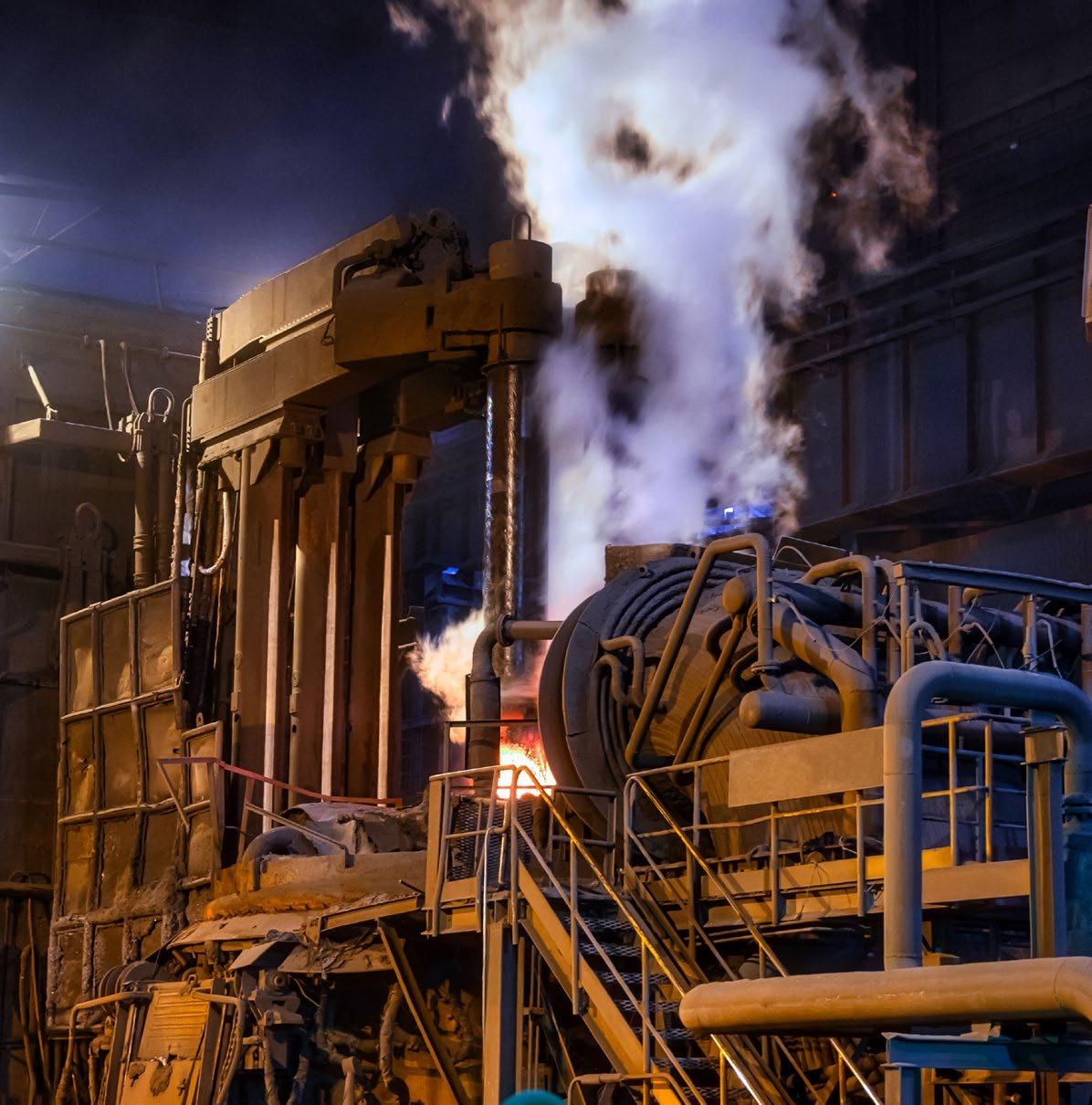
Immagine in copertina: Shutterstock

Gestione editoriale e pubblicità Publisher and marketing office: siderweb spa sb Via Don Milani, 5 - 25020 Flero (BS) tel. 030 25 400 06 commerciale@siderweb.com - www.siderweb.com
La riproduzione degli articoli e delle illustrazioni è permessa solo citando la fonte e previa autorizzazione della Direzione della rivista. Reproduction in whole or in part of articles and images is permitted only upon receipt of required permission and provided that the source is cited.
siderweb spa sb è iscritta al Roc con il num. 26116
n.06 Giugno 2026
Anno 117 - ISSN 0026-0843
Editoriale / Editorial
a cura del Prof. Carlo Mapelli, Politecnico di Milano & President of Italian Association for Metallurgy........ pag.05
Memorie scientifiche / Scientific papers
Siderurgia elettrica / Electric Steelmaking
Optimization of Electric Arc Furnace refining via CFD simulation of steel, slag, and freeboard dynamics
O. Ugarte, T. Okosun, E. Pretorius, J. Maiolo, C. Kovscek, C. Q. Zhou .................................................................
Sulphur control as part of the steelmaking transition: challenge or opportunity
B. Vucinic ..................................................................................................................................................................................
Moving to next EAF digital furnace: first heat at Hybar with SMS group X-Pact AURA
M. G.B. Lugnani, L. Bernardis ................................................................................................................................................
Next generation direct feed power supply for large steelmaking EAFs
P.L. Garmier, D. Basic, C. Baviere, P. Clavier, K. Delsol, N. Lapassat, N. Niberon, C. Sihler, F. Terrien ............... pag.34
Leveraging optical emission spectroscopy (OES) for enhanced process control in Ladle Furnace (LF)
E. Korhonen, T. Ilmakangas, V. Haavisto, M. Jokinen, P. Huhtala ...............................................................................
BSE-EAF – future-proof melting automated system for safe, reliable and efficient steelmaking
R. Schweikle, J. Apfel, A. Pezza ............................................................................................................................................
Secured EAF-performance through process discipline including constraints of raw material and experience
PTI SwingDoorTM: operational results at a leading company in Middle East
P. Marterer, P. Shikhmetoff .................... pag.70
The SMS Electric Arc Furnace for Next Gen minimill
A. Lanari, M. Daita, D. Beacco ............................................................................................................................................... pag.79
Atti e notizie / AIM news
Nota tecnica “Saldatura delle rotaie in campo per interventi di manutenzione celere”, a cura di Guido Capoferri .................................................................................................................. pag.90
Carlo Mapelli torna alla guida di AIM .......................................................................................................... pag.99
Conferimento medaglia d'oro "Walter Nicodemi" a Mario Cusolito................................ pag.100
Eventi AIM / AIM events .......................................................................................................................................
Normativa / Standards ..........................................................................................................................................
As an integral element of the event, the Conference will feature an exhibition, that will enable excellent exposure for products, technologies, innovative solutions or services. For any further information contact Siderweb: commerciale@siderweb.com
Organised by
“L’industria siderurgica europea sta navigando in una crisi energetica, turbolenze geopolitiche e rigorose normative ambientali. Eppure, l’ingegno mostrato in questi atti dimostra che la nostra industria non si limita a sopravvivere: si sta reinventando.”
“The European steel industry is navigating an energy crisis,geopoliticalturbulence, and strict environmental regulations. Yet,theingenuityondisplay intheseproceedingsproves thatourindustryisnotjust surviving; it is reinventing itself.”

Prof. Carlo Mapelli
Politecnico di Milano & EMECR 2026 Co-Chair, President of Italian Association for Metallurgy
Cari Lettori,
International Journal of the Italian Association for Metallurgy
Per oltre un secolo, il forno elettrico ad arco è stato un pilastro della produzione di acciai speciali. Eppure, sfogliando gli atti del 14° Convegno Europeo sulla Produzione di Acciaio con Forno Elettrico (EEC 2026) e della Conferenza Internazionale sull’Efficienza Energetica e dei Materiali e la Riduzione della CO₂ (EMECR 2026), appare chiaro che questa tecnologia non è più solo una via alternativa: sta diventando il cuore pulsante dell’industria siderurgica globale.
Il messaggio del convegno è inconfondibile: il futuro dell’acciaio è elettrico e inserito in una visione di economia circolare. Mentre affrontiamo l’impresa monumentale di decarbonizzare uno dei settori a più alta intensità di emissioni al mondo, questa edizione di La Metallurgia Italiana propone alcuni degli spunti più interessanti presentati a Milano. Conference 2026
Dear Readers,
n. 6 giugno 2020 Organo ufficiale dell’Associazione Italiana di Metallurgia. Rivista fondata nel 1909
For over a century, the electric arc furnace has been a cornerstone of special steel production. Yet, if we glance through the proceedings of the 14th European Electric Steelmaking Conference (EEC 2026) and the International Conference on Energy and Material Efficiency and CO2 Reduction (EMECR 2026), it is clear that this technology is no longer just an alternative route—it is becoming the beating heart of the global steel industry.
The message from the conference is unmistakable: the future of steel is electric, circular, and increasingly intelligent. As we face the monumental task of decarbonizing one of the world’s most emissionintensive sectors, this edition of La Metallurgia Italiana aimstocapturethemosttransformativeideaspresented in Milan.
Le statistiche sono sorprendenti. Come sottolineato nella sessione di apertura, si prevede che la produzione di acciaio elettrico crescerà dagli attuali 550 milioni di tonnellate a quasi 1,8 miliardi entro il 2050. Non si tratta di una semplice crescita, ma di una vera e propria metamorfosi industriale. Tuttavia, questa transizione comporta sfide critiche. La disponibilità di rottame di alta qualità è un vincolo stringente, che costringe l’industria a rivolgersi alla spugna di ferro o a nuove tecnologie di riduzione del minerale in grado di garantire un’impronta carbonica almeno neutrale. Di conseguenza, diversi articoli in questo numero affrontano il cambio di paradigma nel caricamento combinato della spugna di ferro con il rottame, la gestione della scoria e la riprogettazione del forno per adattarsi alle nuove tipologie di carica.
Uno dei temi più dirompenti è la convergenza tra metallurgia e data science. Non più confinata alle analisi a posteriori, l’intelligenza artificiale è uno dei sistemi di gestione del forno. Dall’“ottimizzazione a ciclo chiuso” che adatta dinamicamente le combinazioni di rottame in base a misurazioni in tempo reale della densità, ai sistemi di “visione artificiale” che rilevano autonomamente la contaminazione da rame nel cumulo di rottame, il convegno ha presentato una chiara tabella di marcia verso le prospettive della fusione gestita da agenti di intelligenza artificiale. Questi strumenti non sono solo teorici; casi di studio industriali come quello presentato al congresso da Marcegaglia Sheffield, dimostrano riduzioni tangibili del consumo energetico e dei tempi di fusione.
La parola d’ordine è e sarà decarbonizzazione. Sebbene l’idrogeno sia al centro dell’attenzione come agente riducente per eccellenza – con studi affascinanti sulla fusione riduttiva a plasma d’idrogeno (HPSR) e il ri-riscaldamento con idrogeno al 100% – il convegno ha anche evidenziato ponti pragmatici verso quel futuro. Il concetto di “simbiosi industriale” sta guadagnando terreno, trasformando le scorie e le polveri degli acciai elettrici da rifiuti a risorse preziose per la produzione di
The statistics are staggering. As highlighted in the opening session, electric steelmaking is projected to grow from 550 million tons today to nearly 1.8 billion tons by 2050. This is not merely growth; it is a complete industrial metamorphosis. However, this shift brings critical challenges. The availability of high-quality scrap is a looming constraint, forcing the industry to look towards Direct Reduced Iron (DRI) and Hydrogen-based DRI (H-DRI) or to some new smelting technology ensuring at least a neutral carbon footprint. Consequently, several papers in this issue tackle the paradigm shift of blending sponge iron with scrap, managing the resulting slag chemistry, and rethinking furnace design for ore-based metallics.
One of the most disruptive themes is the convergence of metallurgy with data science. No longer confined to post-heat analysis, Artificial Intelligence is now the co-pilot of the furnace operator. From “closedloop optimization” that dynamically adjusts scrap mixes based on real-time density measurements, to “computer vision” systems that autonomously detect copper contamination in the scrap pile, the conference presented a clear roadmap towards the autonomous meltshop.Thesetoolsarenotjusttheoretical;industrial case studies, such as the one from Marcegaglia Sheffield, demonstrate tangible reductions in energy consumption and tap-to-tap times.
The name of the game is decarbonization. While hydrogen takes centre stage as the ultimate reducing agent—with fascinating studies on Hydrogen Plasma Smelting Reduction (HPSR) and 100% hydrogen reheating—the conference also highlighted pragmatic bridges towards that future. The concept of “industrial symbiosis” is gaining ground, turning EAF slag and dust from waste streams into valuable resources for cement production or secondary raw materials. The integration of biochar as a carbon-neutral foaming agent is another criticalstep,albeitonethatrequirescarefulmanagement of self-heating risks and supply chains.
cemento o come materie prime seconde. L’integrazione del biochar come agente schiumogeno o riducente a impatto di carbonio neutro è un altro passo fondamentale, sebbene richieda una gestione attenta dei rischi di auto-riscaldamento e delle catene di approvvigionamento.
Quando leggerete gli articoli selezionati in questo numero, noterete un filo conduttore: la resilienza. L’industria siderurgica europea sta navigando in una crisi energetica, turbolenze geopolitiche e rigorose normative ambientali. Eppure, l’ingegno mostrato in questi atti – dai convertitori modulari multilevel che stabilizzano le reti deboli ai sistemi di scansione 3D che monitorano l’usura dei refrattari senza esposizione umana – dimostra che la nostra industria non si limita a sopravvivere: si sta reinventando.
Mi auguro che questa sintetica raccolta di lavori serva come prezioso riferimento per ingegneri, ricercatori e decisori mentre navighiamo nel secolo elettrico della siderurgia.
As you read the selected papers in this issue, you will notice a common thread: resilience. The European steel industry is navigating an energy crisis, geopolitical turbulence, and strict environmental regulations. Yet, the ingenuity on display in these proceedings—from modular power converters that stabilize weak grids to 3D scanning systems that monitor refractory wear without human exposure—proves that our industry is not just surviving; it is reinventing itself.
We hope this collection serves as a valuable reference for engineers, researchers, and decision-makers as we navigate the electric century of steelmaking.

edizione 2026
L’ing. Carlo Longaretti è nato il 17 novembre 1924 e la sua vita professionale rappresenta un’esperienza emblematica di interazione tra mondo della ricerca e produzione industriale. E’ stato ricercatore universitario, rappresentante italiano presso la Comunità Europea del Carbone e dell’Acciaio per la gestione dei progetti di ricerca, fu il primo ad introdurre in Italia la produzione e l’utilizzo delle ghise sferoidali e nel 1952 con il cugino Amanzio è stato fondatore della FGS, la fonderia di acciai e ghise speciali sita in Treviglio, tuttora attiva, che ha amministrato sino alla morte avvenuta il 29 marzo 2019. Carlo Longaretti è stata una persona determinata e geniale, in grado di integrare nel proprio lavoro le competenze elettrotecniche, strutturali e metallurgiche attraverso le quali ha sviluppato impianti fusori, tecnologie di solidificazione e nuove leghe per la resistenza alle alte temperature. Grazie alla sua generosità e a quella della famiglia, per ricordare una delle più insigni figure che si sono stagliate nel panorama dell’industria metallurgica italiana del XX e XXI secolo, l’AIM istituisce il Premio Carlo Longaretti.
Il Premio, nella sua terza edizione, verrà conferito in occasione dell’International Workshop Carlo Longaretti 2026 a Bergamo il 3 dicembre 2026 ed include un contributo di €50.000 per sostenere il vincitore nello sviluppo della propria innovazione. L’oggetto dell’innovazione proposta per il concorso può essere un nuovo materiale di natura metallica, oppure un nuovo materiale anche non metallico che abbia un impatto positivo nella produzione o nell’applicazione delle leghe metalliche oppure una nuova tecnologia metallurgica o a servizio del settore metallurgico.
Come concorrere
Il concorso per il premio è rivolto ai Soci AIM (a titolo personale o aziendale) e aperto a diplomati che abbiano frequentato o stiano frequentando un Istituto Tecnico Superiore, studenti di corsi di laurea, laureati, laureati magistrali, dottori di ricerca che dovranno presentare in lingua italiana o inglese:
• curriculum vitae;
• una descrizione dettagliata dal punto di vista tecnico e scientifico dell’innovazione proposta (massimo 15 pagine), che includa:
- elementi che validino l’innovazione e che escludano che si tratti di un’idea di carattere teorico senza prospettive concrete di sviluppo (es. dati sperimentali anche su scala ridotta, immagini, filmati ecc.).
- elementi che comprovino l’originalità dell’innovazione proposta;
- elementi che indichino quali esigenze intenda soddisfare la propria innovazione e quale è l’impatto atteso;
• lista delle proprie pubblicazioni, in particolare di quelle relative all’innovazione proposta.
Il termine di presentazione delle domande, da trasmettersi per email (info@aimnet.it) alla Segreteria AIM, è fissato al 15 ottobre 2026.



Via F. Turati 8 Milano
t. +39 0276397770 / +39 0276021132 info@aimnet.it . www.aimnet.it

O. Ugarte, S. Aryal, T. Okosun, E. Pretorius, J. Maiolo, C. Kovscek, C. Q. Zhou
This study presents a state-of-the-art CFD methodology to simulate the industrial EAF refining stage. The model incorporates jet-induced cavities within a volume-of-fluid representation of the molten steel, slag, and freeboard regions, capturing oxygen-steel reactions, decarburization, oxide formation, and oxide migration from metal to slag and freeboard. Validation against theoretical predictions demonstrates accurate modeling of decarburization and FeO/MnO generation across both high and low carbon regimes. The model is then applied to evaluate reduced oxygen injection scenarios by turning off oxygen jets at 200 sec and 400 sec. Results show that lowering the O 2 injection rate could decrease decarburization performance by ~5% while reducing FeO formation by up to 53%. This FeO reduction lowers carbon-injection requirements for slag foaming, offering potential decreases in operating cost and CO 2 emissions in EAF operations.
KEYWORDS: ELECTRIC ARC FURNACE; SLAG; MOLTEN STEEL; REFINING; VOF; CFD.
In recent years, the steel industry has shifted from the blast furnace-basic oxygen furnace (BF-BOF) route to Electric Arc Furnace (EAF) steelmaking. In the United States, more than 70% of steel production now occurs in EAFs. EAF operations offer improved energy efficiency and operational flexibility and can reduce carbon emissions by up to 55% compared with BF-BOF [1]. The EAF process consists of melting and refining operations. During melting, electrodes and burners supply arc and chemical heat to melt the scrap charge. During refining, burners switch to lance mode, and oxygen is injected into the molten bath to remove carbon, form oxides, and eliminate impurities to reach the desired steel chemistry and temperature before tapping.
EAF refining involves multiple physicochemical processes, making process understanding and optimization challenging. Oxygen-bath interaction, in particular, plays a key role in controlling oxidation reactions which are critical for steel uniformity and quality, and extensive research has been devoted to understanding this process. For instance, Banks and Chandrasekhara [2] performed experiments on gas injection into liquid at right angles and showed that cavity penetration depth decreases
Orlando Ugarte, Shishir Aryal, Tyamo Okosun, Chenn Q. Zhou
Center for Innovation through Visualization and Simulation (CIVS) & Steel Manufacturing Simulation and Visualization Consortium (SMSVC) Purdue University Northwest; Hammond, IN, U.S.A
Nucor Steel Berkeley; Huger, SC, U.S.A
Joe Maiolo
Linde Inc., Tonawanda, NY, U.S.A
Chris Kovscek
Nucor Steel; Jewett, TX, U.S.A
when the liquid is in motion. Alam et al. [3] studied lance angle, lance height, and flow rate effects on wall splashing and found that splashing increases with these parameters up to a critical point, after which it decreases. This study recommended low lance heights and coherent jet nozzles to reduce splashing.
The introduction of coherent jets in the 1990s, which inject oxygen at supersonic speeds, significantly improved EAF productivity by maintaining jet momentum, enhancing bath stirring, and accelerating refining reactions [4]. Oxygen injection also drives iron oxide formation, which is essential for slag formation and slag foaming. Slag foaming insulates the arc, reduces heat losses, and increases productivity. However, excessive FeO leads to yield losses and deteriorates slag foaming behavior. Carbon injections are therefore required to control FeO content and recover iron, motivating extensive research into optimizing practices involving them. Strelbisky et al. [5] implemented Tallman supersonic carbon injectors, achieving substantial reductions in carbon consumption and CO 2 emissions. Linde has also developed a three-in-one supersonic injector that integrates oxygen lancing, carbon injection, and oxy-fuel combustion to reduce carbon losses and improve efficiency of carbon delivery [6]. Research on oxygen injections, cavity formation, and carbon injections has been strongly linked to refining performance. Several models have been developed to optimize refining operations. Memoli et al. [7] created a theoretical model to predict jet penetration and decarburization under various operating conditions. Wei and Zhu [8] developed a thermodynamic model showing how competition among C, Cr, Si, and Mn for oxygen evolves during refining in the AOD process; they identified a critical carbon concentration range (0.25-0.4% C) where decarburization becomes mass-transfer-controlled.
Prior research at the Center for Innovation through Visualization and Simulation (CIVS) at Purdue University Northwest developed advanced CFD models for industrial EAF refining operations. Chen et al. [9-11] introduced an integrated method dividing the refining process into three sequential calculations: supersonic coherent jet, cavity formation in bath due to jet impingement, and stir-
ring and reactions in refining simulations, avoiding the need to directly model high-speed oxygen injection in EAF refining. Moreover, the effect of oxygen flow rate on bath mixing [12] and the trade-offs between oxygen flow rate, decarburization performance, and FeO-related yield losses [13] were also studied. However, these studies did not account for the direct interaction between the metal and slag phases. In particular, the previous approach considered only the molten bath and the injected gas, while oxides were removed through the top boundary to mimic the effect of the slag layer. The present study introduces a CFD framework that explicitly incorporates metal-slag interactions during refining operations. This is achieved by applying the Volume of Fluid (VOF) methodology to capture the metal, slag, and gas phases simultaneously. Unlike the previous approach, this methodology does not impose limitations on phase interactions, allowing phenomena such as mixing, stirring, oxide formation, and oxide transport to the slag and freeboard regions to be directly resolved. The model is applied to an industrial EAF operation provided by Nucor Jewett and validated against theoretical predictions. The validated model is then used to investigate the impact of reduced oxygen flow rates on refining performance.
Based on a previous approach [9], the oxygen injection produced at supersonic velocities is separated from the refining simulation by applying a three-step process. First, coherent-jets simulations are performed to determine the jet velocity and composition of injected oxygen when it reaches the bath surface. Second, the results provided by coherent-jet simulations are used to determine the cavities forming in the surface of the bath as a result of oxygen injection. Third, the computed cavities are added to a refining CFD domain where oxygen injected at the cavities interact with molten steel to generate oxides. The refining simulation includes the molten steel, slag and freeboard and oxidation reactions of Fe, C and Mn. Figure 1 shows these steps. Further details, including mathematical formulation, are included in Ref [9, 12-13].
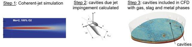
Fig.1 - Three steps methodology used in CFD simulations of EAF refining process.
Computational domain:
As mentioned earlier, steps 1 and 2 provide the cavities forming in the surface of the molten bath due to supersonic oxygen injection. These cavities are included in the CFD domain of the refining simulation (step 3 in figure 1). Figure 2a shows the computational domain of the EAF refining simulation. The cavities are pre-calculated based on four
coherent-jets injecting oxygen at 1000 SCFM. The domain geometry and operation parameters were provided by Nucor Jewett. The CFD domain has 0.9 million non-structured cells, where solid surfaces are assumed to be adiabatic walls. Figure 2b shows key dimensions, and the location of the 4 cavities formed by the coherent-jets are shown in figure 2c.
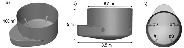
Fig.2 - Computational domain used in refining simulations including location of cavities due to oxygen injection.
The CFD refining model is validated against theoretical predictions [14]. Namely, a typical operation is simulated in Nucor Texas (NSTX) EAF without injection of carbon
particles and compared with decarburization and FeO production predicted by theory. Table 1 lists key parameters applied in the validation case.
Tab.1 - Parameters used in the validation (baseline) simulation.
BASELINE OPERATION PARAMETERS
Variable Value
Number of coherent jets 4 O2
Results of the validation are shown in figure 3. The CFD results accurately predict the decar-burization process (figure 3a), capturing the rapid carbon removal from the mol-
ten steel during the first two minutes. Once the dissolved carbon reaches 0.3%, decarburization becomes controlled by carbon transport within the bath rather than by gas avail-
ability. At low carbon levels, the rate slows as carbon must diffuse to the O2 injection sites, leading to the reduced decarbu-rization rate observed after two to three minutes. Figure 3b shows the FeO increase in the slag. Although the initial FeO rise is overpredicted, the model aligns with theoretical trends as lower carbon content allows more FeO to form. It should be noted that the CFD results are com-
pared against theoretical predictions that do not account for carbon injection. In industrial EAF operations, carbon injection is commonly employed to control FeO levels, promote slag foaming, and minimize metallic yield losses. Furthermore, the formation of other oxide spe-cies, including CaO, Al2O3, MgO, and SiO2, is not considered in the set of chemical reactions included in the present CFD model.
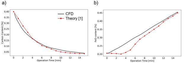
Fig.3 - CFD prediction of decarburization and FeO content compared with theoretical prediction reported in Ref [14].
Decarburization and FeO production in baseline simulation
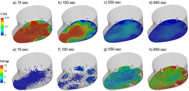
CFD results for the baseline case show clear spatial and temporal variations during the refining operation (figure 4). In the first two minutes, carbon content decreases rapidly (figure 4a-b), while changes slow significantly afterward, particularly during the final five minutes of the 15-minute
refining period (Figure 4c-d). The opposite trend appears in FeO production. Initially, the FeO production rate is low (figure 4e-f), but it significantly increases as the decarburization rate declines and oxygen reacts primarily with Fe in the molten steel (figure 4g-h). Figure 4 also shows that reactions do not occur uniformly throughout the bath, but they are driven by oxygen injections forming cavities near the furnace walls.
Simulation results
and
Decarburization and FeO production in baseline simulation
The spatial and temporal variations of oxidation reactions in figure 4 demonstrate that refining can be optimized by dynamically adjusting oxygen injections during the process. For instance, oxygen injections can be reduced after 2-3 minutes since oxidation reactions mostly lead to FeO after this period. However, the reduction of oxygen injections can also lead to poor bath stirring which affects the refining performance. Figure 5 compares the baseline case with two cases where oxygen injection is reduced by
turning jets off during the operation. The first reduced oxygen case turns jets 1 and 3 off at 200 sec, and the second case turns jets 1 and 3 off at 400 sec (see figure 2c for jet locations). Figure 5 compares the carbon and FeO fields at 600 sec for the three cases. Figures 5a-c show how carbon content increases as less oxygen is injected. The larger difference is seen in figure 5b where oxygen rate is reduced at earlier time. The corresponding FeO production results are shown in figures 5d-f. Here, both cases with reduced oxygen injection show significant reduction of FeO content as compared with baseline cases.
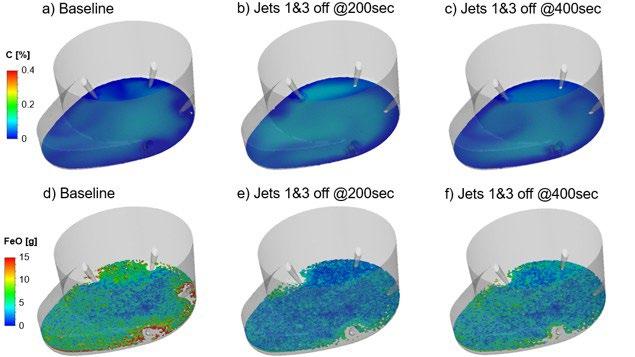
Fig.5 - Comparison of baseline and cases with reduced oxygen injection at 600 sec.
Figure 6 shows the carbon and FeO trends along the refining operation for the three cases compared in figure 5. The reduced oxygen scenarios are shown in orange lines, where solid line indicates jets turned off at 200 sec and dashed line shows the case with jets turned off at 400 sec.
The larger impact of reducing oxygen is seen in the FeO production. This is expected as decarburization at later stage is significantly less efficient as concluded from figures 4a-d.
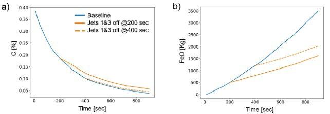
Fig.6 - Carbon and FeO trends along refining operation for baseline case (blue), case with jets 1 & 3 off at 200 sec (orange-solid) and case with jets 1 & 3 off at 400 sec (orange- dashed).
Table 2 quantifies the impact of lowering oxygen injection. Specifically, turning off two of the four oxygen jets at 200 sec reduces decarburization by 5.5% relative to the baseline case. Also, the reduction of oxygen injection at 200 sec lowers FeO production by 53.6%. If the changes are applied later at 400 sec, the impact on decarburization is 2.1%, and FeO still shows a large impact as it is reduced by 41.5% relative to the baseline case.
Tab.2 - Variation in decarburization and FeO production due to lowered oxygen injection.
Variations in decarburization and FeO production have an impact on slag foaming as well. Slag foaming is driven by bubbles produced mostly due to carbon reactions in the molten bath and by suspended particles. It benefits EAF process as the foamed slag shrouds the electric arc and prevent thermal losses. Slag height is computed based on procedure shown in Ref [15]. The slag viscosity used in this formulation has been modified to include the impact of suspended particles by using the formulation of Krieger and Dougherty [16]. Figure 7 shows the slag height for the baseline (figure 7a) and the case with two jets turned off at 200 sec (figure 7b). Carbon injection is considered in these calculations as it is required to sustain slag foaming by boosting carbon reactions while preventing excessive FeO in slag. Carbon injection efficiency is considered by including 70% and 90% efficiency cases, which determines how much injected carbon is actually used in slag reactions. Results show that slag height increases rapidly in the beginning due to high decarburization at early stage. As the refining process progresses, CO bubbles in slag escape and slag foaming is lowered. In the baseline, 715 kg of carbon particles are injected, and the slag height is maintained above 0.5 m for the 90% carbon injection efficiency (figure 7a). For the case with reduced oxygen injection (figure 7b), 455 kg of carbon injection is needed to obtain similar slag height, reducing the additional carbon injection by 36%. The reduction of injected carbon reduc-
es operation costs but also reduces the carbon emissions in EAF operations, as carbon injections can account for ~40% of EAF emissions [17]. Therefore, reducing the oxygen injection rate during refining may offer opportunities for process optimization. However, it should be noted that oxygen injections also play a critical role in promoting bath stirring and, consequently, temperature homogenization within the molten steel. This effect is particularly important in AC furnaces, where electromagnetic stirring is less significant than in DC furnaces. Changes in oxygen injection rates can alter the thermal distribution within the molten bath because the heat released by oxidation reactions is transported through the bath by fluid motion. As a result, reduced stirring may lead to larger local temperature gradients, which can affect refining efficiency and final product quality. Therefore, thermal homogenization should be considered alongside refining performance when determining optimal oxygen injection practices.
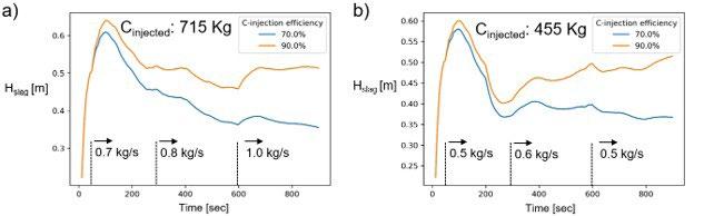
Fig.7 - Slag height for baseline case and case with jets 1 & 3 off at 200 sec, including carbon injection. Two carbon efficiencies are considered for each case, 70% and 90%.
In this study, a CFD framework is applied to analyze refining operations in an industrial Electric Arc Furnace (EAF) provided by Nucor Jewett. The model extends previous work by explicitly incorporating the slag and freeboard regions in addition to the molten steel phase and the chemical reactions considered in earlier studies. This enhanced approach enables the direct resolution of key refining mechanisms, including bath stirring, phase mixing, and their influence on oxidation reaction rates. The framework employs a Volume of Fluid (VOF) methodology to capture the gas, slag, and molten steel phases, model the oxidation of carbon, iron, and manganese within the molten steel, and track the transport of the resulting oxides into the slag and freeboard regions.
A baseline case was modeled in which four coherent jets supply oxygen at 1000 SCFM each. The injected oxygen interacts with 144 tons of molten steel containing 0.41% C and 0.25% Mn, along with 28 tons of slag, over a 15-minute refining period. CFD results were validated against theoretical predictions reported in Ref. [14]. Validation shows very good agreement for decarburization in both high-carbon (C > 0.3%) and low-carbon regimes, as well as accurate prediction of the overall FeO increase in the slag. Although the model overpredicts the initial FeO production rate, it produces correct FeO levels by the end of refining.
The baseline case also demonstrates the strong time and space nature of the refining process. During the first two minutes, decarburization is rapid, and slag FeO increases slowly. Oxidation reactions occur primarily near the injection locations and are transported toward the furnace center by gas-driven stirring. During the last 10 minutes, FeO content in the slag rises significantly as carbon reactions diminish due to the low carbon concentration in the bath. The validated CFD model was then used to evaluate two additional scenarios in which oxygen injection was reduced by shutting down coherent jets. In the first case, coherent jets 1 and 3 were turned off at 200 sec; in the second, both jets #1 and #3 were turned off at 400 sec. Decarburization rates and FeO generation were compared with the baseline case, yielding the following results:
• turning off jets 1&3 at 200 sec while keeping the remaining jets active reduced decarburization performance by 5.5% and lowered FeO generation by 53.6%;
• turning off the same 1&3 jets at a later time, 400 sec, reduced impact on decarburization, 2.1% less, and led to a 41.5% reduction in FeO generation.
The impact on decarburization and FeO production was followed up by computing the slag height during the process for the baseline case and the case where jets 1 and 3 were turned off at 200 sec. These results show that it is possible to predict a relationship between oxygen use and carbon injection which could be used to optimize
the refining cycle for operational cost, productivity and emissions reduction. Future work might include taking into consideration the impact of carbon and oxygen lance practice and slag composition and temperature in respect to overall slag foaming and furnace operation. These results, along with additional scenarios simulated using the CFD platform, can be used to optimize the refining stage. While the influence of oxygen injections on refining performance observed in this study is expected to be representative of industrial EAF operations in general, the quantitative optimization trends are likely to be furnace-specific. Factors such as furnace size, coherent-jet and lance configuration, operating practices, and the target slag and molten bath conditions can significantly influence the optimal oxygen injection strategy and the resulting refining performance.
The authors thank the members of the Steel Manufacturing Simulation and Visualization Consortium (SMSVC) for their support and consultation on this research. In addition, the authors would like to thank the staff and students at Purdue University Northwest’s Center for Innovation through Visualization and Simulation (CIVS) for their support and for providing the resources necessary to conduct this research. This work was supported by the U.S. Department of Energy’s Office of Critical Minerals and Energy Innovation under the Industrial Technologies Office (ITO) Award Number DE-EE0011212. The views expressed herein do not necessarily represent the views of the U.S. Department of Energy or the United States Government.
[1] M. Fan, Z., Friedmann, S. J. (2021). Low-carbon production of iron and steel: Technology options, economic assessment, and policy. Joule, 5(4), 829-862.
[2] Banks, R. B., & Chandrasekhara, D. V. (1963). Experimental investigation of the penetration of a high-velocity gas jet through a liquid surface. Journal of Fluid Mechanics, 15(1), 13-34.
[3] Alam, M., Irons, G., Brooks, G., Fontana, A., & Naser, J. (2011). Inclined jetting and splashing in electric arc furnace steelmaking. ISIJ international, 51(9), 1439-1447.
[4] Mathur, P. C., Mahoney, W. J., Warty, S. K. and von Schéele, J. (2021). CoJet® - 25 Years of Revolutionizing EAF Steelmaking. Steel Tech Vol. 15, No 4
[5] Strelbisky, A., Strelbisky, M., & Kurisu, K. (2024). Decarbonization at Nucor Seattle using Tallman Supersonic Carbon Injectors (TSCi). In 13th European electric steelmaking conference. Stahlinstitut VDeh, Essen.
[6] Maiolo, J., Hirmiz, R., & Bielec, B. (2025). 3-in-1 Injector for EAF: Development, Laboratory Testing and Industrial Trials. In 2025 Iron and Steel Technology Conference, AISTech 2025 (pp. 635-644). Association for Iron and Steel Technology.
[7] Memoli, F., Mapelli, C., Ravanelli, P., & Corbella, M. (2004). Simulation of oxygen penetration and decarburization in EAF using supersonic injection system. ISIJ international, 44(8), 1342-1349.
[8] Wei, J. H., & Zhu, D. P. (2002). Mathematical modeling of the argon-oxygen decarburization refining process of stainless steel: Part II. Application of the model to industrial practice. Metallurgical and materials transactions B, 33(1), 121-127.
[9] Chen, Y., Silaen, A. K., & Zhou, C. Q. (2020). 3D integrated modeling of supersonic coherent jet penetration and decarburization in EAF refining process. Processes, 8(6), 700.
[10] Chen, Y., Wang, Y., Tang, G., Silaen, A. K., Vanover, K., & Zhou, C. Q. (2019). Numerical investigation of decarburization reaction characteristics in electric arc furnace steelmaking process. Association for Iron & Steel Technology. AISTech 2019 Proceedings, 789796.
[11] Tang, G., Chen, Y., Silaen, A. K., Krotov, Y., Riley, M. F., & Zhou, C. Q. (2019). Investigation on coherent jet potential core length in an electric arc furnace. Steel Research International, 90(4), 1800381.
[12] Ugarte, O., Busa, N., Konar, B., Okosun, T., & Zhou, C. Q. (2024). Impact of Injection Rate on Flow Mixing during the Refining Stage in an Electric Arc Furnace. Metals, 14(2), 134.
[13] Kottapalli, S., Ugarte, O., Konar, B., Okosun, T., & Zhou, C. Q. (2025). CFD Modelling of Refining Behavior in EAF: Influence of Burner Arrangement and Oxygen Flow Rates. Metals, 15(7).
[14] Pretorius, E., Oltmann, H., & Jones, J. (2010). EAF fundamentals. LWB Refractories, Hilden, 14.
[15] Luo, Q., Chen, Y., Abraham, S., Wang, Y., Petty, R., Silaen, A. K., & Zhou, C. (2022). Effects of EAF operations on water cooling panel overheating. steel research international, 93(9), 2100844.
[16] Krieger, I. M., & Dougherty, T. J. (1959). A mechanism for non-Newtonian flow in suspensions of rigid spheres. Transactions of the Society of Rheology, 3(1), 137-152.
[17] Demus, T., Echterhof, T., Pfeifer, H., Schulten, M., Noel, Y., & Quicker, P. (2012, September). Investigations on the use of biogenic residues as a substitute for fossil coal in the EAF steelmaking process. In Proceedings of the 10th European Electric Steelmaking Conference, Graz, Austria (pp. 25-28).
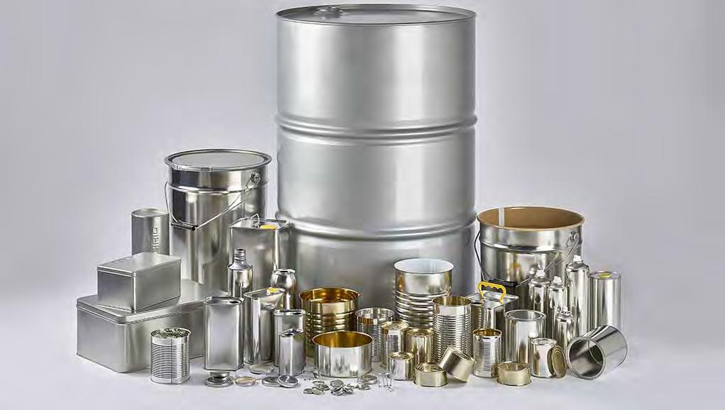
IFTSR 2026 will bring together industry leaders, researchers, recyclers, regulators, and brand owners to discuss the main technological, environmental, commercial, and regulatory challenges facing tinplate and metal packaging.
The Forum will address the impact of anti-dumping measures, CBAM, energy costs, and raw material volatility on global supply chains and competitiveness. Key discussions will focus on advanced lacquer technologies, BPANI solutions, food contact compliance, corrosion mechanisms, and shelf-life performance. Special attention will be devoted to sustainability and circularity, including low-carbon production, eco-design, eco-labeling, recycled content valorization, and strategies for reducing the environmental footprint of metal packaging. The growing role of Artificial Intelligence and digital technologies in quality control, defect detection, predictive maintenance, and smart manufacturing will also be explored. Dedicated sessions will examine pre-consumer and post-consumer recycling, de-coating and sorting technologies, as well as the evolving regulatory framework related to bisphenols, PFAS, food contact materials, and the Packaging and Packaging Waste Regulation (PPWR).
IFTSR 2026 aims to promote collaboration across the value chain and contribute to a shared roadmap for innovation, sustainability, regulatory compliance, and market resilience in the metal packaging sector.
Submission of abstracts: .................................... 18 September 2026
Information on acceptance: ...........................29 September 2026
Opening online registration: ............................29 September 2026
Submission of pdf presentations: 6 November 2026
Early bird registration: 6 November 2026
Submission of full papers (optional): After the Workshop
organised by
Associazione Italiana di Metallurgia Via Filippo Turati 8 Milano - Italy t. +39 0276397770 t. +39 0276021132 conference@aimnet.it www.aimnet.it

Improving the quality of steel has been a matter of routine for metallurgical engineers and steelmaking companies in a demanding market for quality products. The traditional Electric Arc Furnace process has the lowest carbon emission compared to the integrated route, making it the best route for green steel production. In addition, the industry is focused on ensuring that high-quality steel products can be produced smoothly, immediately after the transition. One of the challenges is controlling sulphur residual in steel, which is critical for certain applications and has “secondary / additional” impact on overall steel cleanliness. Lesson learned from market with different feasibility studies, investigations and accumulated know how from long list of projects for different flat products, including thick and thin casting processes are summarized and reported in article.
KEYWORDS: EAF PROCESS; SULPHUR CONTROL; SLAG QUALITY CONTROL.
INTRODUCTION: THE IMPORTANCE OF SULPHUR CONTROL
Sulphur influences microstructure primarily through the formation of MnS inclusions, which tend to segregate along grain boundaries and within the matrix. These inclusions can modify grain growth behaviour during hot working and heat treatment, often acting as pinning points that inhibit grain coarsening. Mechanically, sulphur reduces toughness and ductility due to its embrittling effect, especially at higher concentrations. It can promote hot shortness, leading to cracking during hot working processes. Physically, sulphur presence can decrease thermal and electrical conductivity slightly, owing to the non-metallic inclusions. It also influences magnetic properties by affecting the microstructure of steel and inclusion distribution. Chemically, sulphur reduces corrosion resistance, especially in environments where sulphide inclusions act as initiation sites for localized corrosion. Oxidation behaviour is also affected, as sulphur compounds can promote scale formation and spallation during high-temperature oxidation. In steel grades with a higher content of sulphur and aluminium it is difficult to form liquid inclusions with calcium, without forming CaS [1]. It is well known that the addition of calcium can prevent the precipitation of MnS.
Italy, 33042
Compared to MnS, CaS inclusions are harder and less deformable. Duplex types of CaS or (Ca,Mn)S inclusions can exist as a single-phase inclusion. Since large oxide inclusions surrounded by calcium sulphide were identified as of primary origin [2], CaO-Al2O3, acts as nuclei for the precipitation of calcium sulphide, with the result that the CaS phase is confined to the outer surface. Over-addition of calcium can lead to the formation of solid CaS inclusions which are detrimental to the castability of steel. Additionally, excess calcium can react with the alumina contained within slag and refractory, increasing the number of inclusions formed in the steel and reducing cleanliness [3].
Sulphur content from the primary melting unit
Charge mix evaluation for an EAF melt shop is based on steel quality requirements and on the refining capability of the chosen secondary metallurgy units. The integrated steelmaking process presents intermediate steps between the Iron Making and Steel Making division – Sulphur removal from hot metal. The capability to remove sulphur from hot metal is strong and final sulphur content prior to hot metal charging into the BOF could be low – up to 0.002%.
Tab.1 - Main reasons for having different sulphur content before tapping from primary melting unit.
BOF (usually, sulphur content is lower) EAF (usually, sulphur content is higher)
Raw material
Charge mix
Raw material quality
Type of raw material
Slag basicity during steelmaking process
MgO content in slag
Slag density
Oxides in slag
Carbon Vs. Oxygen
Steel temperature
Steel volume mixing
Hot metal with low sulphur content
High participation of hot metal
Controllable inlet sulphur content
Hot metal, scrap and slag builders
High / Favourable for sulphur removal
Aligned with sulphur removal
Higher - Better for sulphur removal
Lower content - Better for sulphur removal
Closer to equilibrium
Higher temperature before tapping
Stronger agitation
The impact of raw material quality on sulphur content control during the primary melting process can be observed in the case of the BOF process as well. With, on average, 20% of scrap participation in the charge mix, the impact of sulphur content in scrap and slag builders is
Different kind of raw material
High participation of sulphur bearing material
Unpredictable sulphur content
Different charge mixes, slag builders, slag foaming agent
Low / Not sufficient for sulphur removal
Higher content - Based on slag basicity
Lower - to control slag foaming
Higher content
Higher content of oxygen with same carbon content
Lower temperature before tapping
Less agitation
strong. In the case of the EAF process, sulphur removal is lower and less predictable. The figures below report typical sulphur content before tapping from different primary melting units.
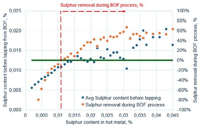
Fig.1 -Typical (average) sulphur content before tapping from BOF (internal database).
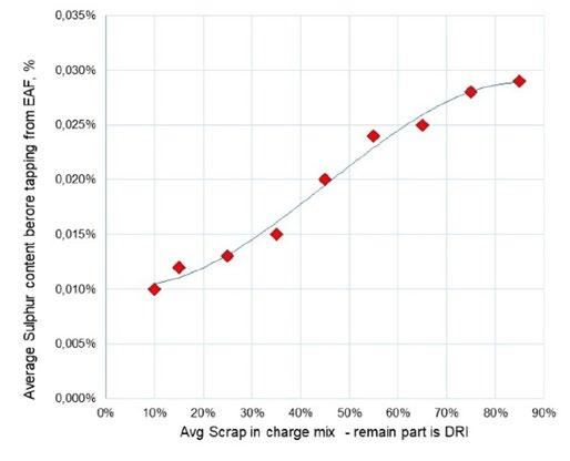
Fig.2 -Typical (average) sulphur content before tapping from EAF (internal database).
Scrap participation in the EAF charge mix is linked to the refining capability of the secondary metallurgy process and with steel quality requirements.
The Electrical Arc Furnace process could have the same productivity as the BOF process has. A different charge mix and different primary steelmaking metallurgy result in different outputs from the primary melting unit. Obviously, a higher sulphur removal rate is required in the case
of the EAF based process and it could require a longer process time and higher stirring energy. Stronger contact between steel / slag and refractory material could have an impact on steel quality (i.e. generated MgO based inclusions or higher refractory wearing). To overcome this issue, a tailor-made melt shop must be designed, and a dedicated steelmaking practice must be applied. Metallurgical preconditions for sulphur removal are slag basicity, low content of free oxygen and low oxides content in slag, temperature, and stirring energy. Natural, strong mixing during tapping, together with extended mixing
time after tapping, will promote a higher sulphur removal rate and could provide a “suitable” initial sulphur content
for the ladle furnace process. This is possible to do with a proper layout design.
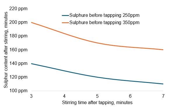
Fig.3 - Case study: Impact of stirring time after tapping on sulphur removal during tapping and during mixing after tapping.
Strong sulphur removal during the secondary metallurgy process is influenced by slag quality, stirring energy, and equipment design. For example, with the same melt shop productivity, the twin ladle furnace solution enables a
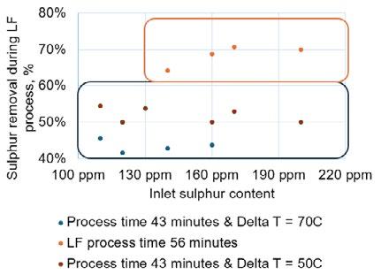
Fig.4 - Impact of different process time durations and different super heats on sulphur removal rate – based on top slag sulphur removal practice – Case study.
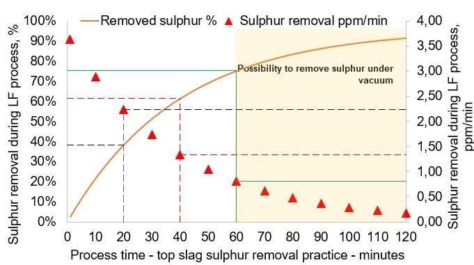
The effectiveness of sulphur removal during secondary steelmaking is influenced by the available process time under conditions that favour sulphur transfer from the metal phase to the slag phase. A critical aspect is the
longer available process time and higher sulphur removal rate. The main reason for a higher, available process time are “hidden” operative steps by presence of two roofs and two transfer cars.
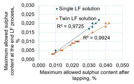
Fig.5 - Different sulphur removal with the same metallurgical conditions: Single ladle furnace versus Twin ladle furnace design – Case study.
time-balance between two competing process requirements:
• the time required for reheating (thermal compensation);
• the time available for intensive steel–slag mixing (mass-transfer driving stage).
The ratio between reheating vs. strong mixing time directly affects the degree to which the slag can be fully activated (high CaO activity, low FeO), the mass transfer
of sulphur across the interface, and the approach toward equilibrium sulphur levels. A high reheating-to-mixing ratio reduces the efficiency of desulphurization even if slag composition is optimal.
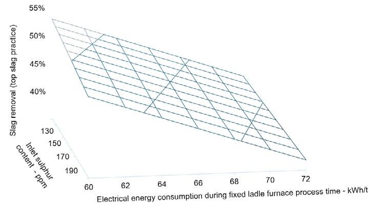
Fig.6 - Case study: Impact of different power on time duration, expressed as consumed energy on sulphur removal (fixed process time with fixed applied power).
Slags in ladle metallurgical processes are designed to maximize their refining capacity, which includes an optimized chemical composition as well as physical properties. In a clean steel process slag should not contain excessive amounts of unstable reducible oxides (FeO, MnO). The effective viscosity of the slag increases by addition of refractory oxides (MgO and CaO) beyond the liquidus composition, whereas the addition of fluxing oxides increases the fluidity of the slag. The higher the oxidation potential, the smaller the sulphur distribution ratio between steel and slag. Thus, oxygen in the form of oxide in slag, and oxygen in metal significantly reduce the degree of desulfurization.
The sulphide capacity of slag (CS) is one of the most important characteristics of refining property of the slags applied during extra-furnace steel processing. This value is determined as the function of slag temperature and composition, i.e. this value is experimentally determined and thermodynamically evaluated. Figure 7 reports the impact of slag composition on sulphide capacity. Reference conditions for the study reported below is as follows: slag with FeO = 0.5% and (CaO+MgO)/(SiO2+Al2O3) = 1.3.
Deep sulphur removal is possible during the ladle furnace process by applying an injection of materials which have strong affinity towards the sulphur. Splashing during material injection consequently has a high nitrogen pick up and shall be considered as a kind of “secondary re-oxidation”. Certainly, the best process is sulphur removal based on “top slag practice” only, if total steel residence time and applied stirring energy do not affect final steel quality.
Sulphur is well known as a surface-active element in molten steel, meaning it strongly affects reactions occurring at the metal-gas interface, where nitrogen is removed during vacuum degassing. A kinetic study on nitrogen removal under reduced pressure showed that sulphur, as a surface-active element, reduces the surface reaction rate of nitrogen. Confirmation for this statement has been found by statistical evaluation of internal databases from different projects with the same metallurgical conditions.
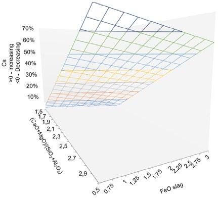
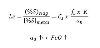
Fig.7 - Evaluated impact of slag composition on sulphide capacity of slag (internal data evaluation) [4]
Note: Chart must be considered as indication only; multiple R = 0.65; P-value for each coefficient 6.4x10(-8) or less; reference sulphide capacity based on FeO content = 0.50%.
It is well known that sulphur removal does not exist during the RH (recirculation) vacuum process which has an impact on limited nitrogen removal under vacuum, compared with the application of the vacuum tank degassing process. In the case of an RH-type degassing unit, an extremely low sulphur content—in the range of 20÷30ppm prior to degassing—must be obtained. A strong agitation needed for deep sulphur removal, with fixed available process time, could have an impact on steel quality (flat
products with high required formability).
Thanks to intensive contact between steel and slag, continuous slag reduction and continuous sulphur removal are part of the vacuum tank degassing process. Sulphur removal during the vacuum process has an impact on nitrogen removal as well. The figure below reports the impact of “effective surface” on nitrogen removal under vacuum (vacuum tank degassing) together with the impact of different, inlet nitrogen content.
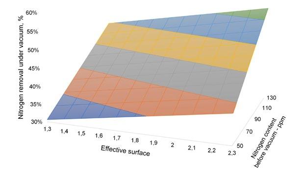
With the LF-VTD (vacuum tank degassing) secondary metallurgy process route overall sulphur removal can be divided in three steps: during tapping, during the ladle furnace process, and during the vacuum process, so optimum sulphur removal during each process step could be applied. In this way it is possible to achieve the ultra-low final sulphur content needed for grades like pipe grades for sour applications and at the same time to have controllable agitation and applied stirring energy during the ladle furnace process. Due to the need to control the “intensive” contact between steel / slag and ladle refractory material, as part of the steelmaking transition, existing ladles are quite often modified. Several types or different num-
bers of porous plugs are added to release the mechanical stress on the refractory material through a higher specific argon flow rate.
Figure 9 shows the possible critical sulphur content to be achieved during the ladle furnace process and additional sulphur removal under vacuum in the case of the vacuum tank degassing process. With the twin ladle furnace design (or application of two stations) it is possible to achieve an extremely low sulphur content at the end of ladle metallurgy process. However, production running costs, together with steel residence time, must be considered as parameters as well.
The removal of sulphur in secondary metallurgy is a crucial refining step aimed at improving steel quality. Sulphur is an undesirable impurity because it causes hot shortness, reduces toughness and ductility, and deteriorates weldability.
For the integrated steelmaking process, sulphur control is based on sulphur removal from hot metal. As part of the steelmaking transition, the secondary steelmaking process must be modified as well, and the sulphur removal process (by keeping the same final steel quality) must be considered as an important part of the steelmaking transition step.
Shortage of clean material consequently has an impact on
higher sulphur content prior to tapping from the Electric Arc Furnace. Temperature control together with proper slag forming (on time), ladle design, maximum allowed and optimum steel residence time, together with proper design of vacuum degassing station must be considered as crucial steps during Best Available Technique development.
The Electric Arc Furnace process is confirmed as a “green steel technology”. Circular economy, raw material supply, steel quality control, and tailor-made or modified secondary metallurgy process together with an EAF design based on quality and productivity needs are important steps needed to keep high steel quality as it is with integrated process.
[1] S. Yanq, L. Zhanq, Q. Wanq and Y. Chen, “Transient Phenomena of inclusions in Alloy Steels during RH-VD-CC Processs,” AISTech 2012 Conference Proceedings, Vol. I, pp.1151-1160. DOI:10.1002/srin.201300030
[2] H. Zhou; “Modification of non-metallic inclusions to improve the fatigue properties of nitriding steels,” Master of Engineering; University of Canterbury; October 1993 http://dx.doi.org/10.26021/2991
[3] S. K. Choudhary, A. Ghosh; “Thermodynamic Evaluation of Formation of Oxide–Sulfide Duplex Inclusions in Steel,” ISIJ International, Vol. 48 (2008), No. 11, pp. 1552–1559. https://doi.org/10.2355/isijinternational.48.1552
[4] B. Vucinic; “High quality low carbon flat grades based on EAF-LF-VD process route,” 13th European Electrical Steelmaking Conference, June 2024, Essen.
M.
The paper presents the new EAF digital furnace implemented at Hybar’s new 630,000 tpy rebar micromill in Osceola, Arkansas. The X-Pact® AURA was pre tuned before delivery using advanced development and testing methods with RTDS simulations (Real Time Digital Simulator), which allowed it to be commissioned in just two days and the EAF to be rump up in four heats only. The X-Pact® AURA family of IGBT based power modules is capable of feeding EAFs from 5 MVA up to 350 MVA. This fully modular technology provides the required efficiency, dynamic control, and flexible power to meet the needs of the green steel transformation and grid code requirements. Using this innovative technology and proprietary control algorithms, which take full advantage of power electronic capabilities, ensures the highest power transfer and the lowest impact on grid, especially regarding flicker limits. Hybar’s steelmaking facility operates entirely on renewable energy, made possible by the seamless integration of a solar farm with X-Pact® AURA clean and flexible EAF power supply. Moreover, EAF performance has been improved by the addition of fault ride through capability, which demonstrated power supply resilience and enhanced plant availability by avoiding EAF stoppages.
KEYWORDS: EFFICIENCY; GREEN STEEL; ENERGY SAVING; DIGITAL EAF POWER SUPPLY; POWER QUALITY.
Due to the increasing incorporation of renewable energy resources in power grids, which are becoming weaker, the efficient, dynamic, and flexible supply of power to Electric Arc Furnaces is a must. X-Pact® AURA (AURA in the text) help steelmakers to deal with this challenging environment.
The AURA system is designed to achieve efficient and stable power control to feed DC arc furnaces in all power networks configurations, including weak grids. Based on modern IGBT technology, the new design achieves world class performances in terms of high dynamics control, efficiency, reliability, redundancy and minimum impact on electric network quality.
The modular and redundant design allows also partial load operation in case of a module failure, without interruption of the process (fault ride through), which is increasing the availability and due to repetition of same components in the systems the number of spares is significantly reduced. In this case no SVC or Statcom was necessary to comply with grid requirements.
In view of digitalization of steelmaking power supply, SMS decided to implement a real-time digital twin for the AURA power conversion system. This high-fidelity platform is intended to work as demonstrating facility for process automation and power system simulator for the EAF. RTDS (Real-time digital simulator) offers a method to predict and later validate the system performances and to reduce the commissioning time. Other than special testing tools, it’s worth mentioning that each power converter is type-tested at factory, including rated-load current temperature rise test.
The AURA power converter is composed of a 24-pulse diode rectifier and DC-DC chopper converter: it includes a fast discharge circuit for DC-link capacitor discharging and a pre-charging circuit. The AURA power converter cabinet includes the control cubicle, the water-cooling cubicle and a small air conditioning cubicle, everything assembled in an IP54 enclosure. The AURA power converter output 16kAdc with a maximum voltage of 1000Vdc. Figure 2 shows an open-door front view of the cabinet.
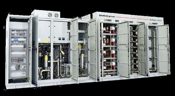
Each power converter is fed by an AFWF dry-type transformer. The EAF power is fed by 6 AURA power converters connected in parallel through a high current busbar system with no additional reactor. The AURA power conversion system adopts the N-1 con-
figuration, meaning that the system can deliver full power even if one of the power converters is out of service. This configuration is made possible thanks to Fault-ridethrough functionality. An extremely high redundancy level is chosen by design: communication with process
PLC is redundant, redundant controllers with hot backup configuration are adopted for each power converter and all the controllers can switch between two internal
sub-networks. Of course, redundant cooling pumps and redundant sensors are applied to deionized-water cooling circuits.
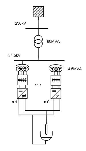
- Principle Single line diagram.
Project development roadmap
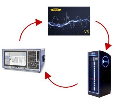
It’s foreseen a model-based design approach for power system: it integrates the whole development procedure, from basic design to site validation, passing through control code development, laptop Electro Magnetic Tran-
sient simulation and in the end RealTime Hardware-inthe-Loop testing. This development procedure allows us to have both short-term and long-term performance figures first simulated, then measured at site for validation.
The design process started with a measurement campaign, with high sampling rate device, on an existing DCEAF with a similar size and charge mix. This allows us to include the control action by the X-Pact® SynReg electrode regulator model.
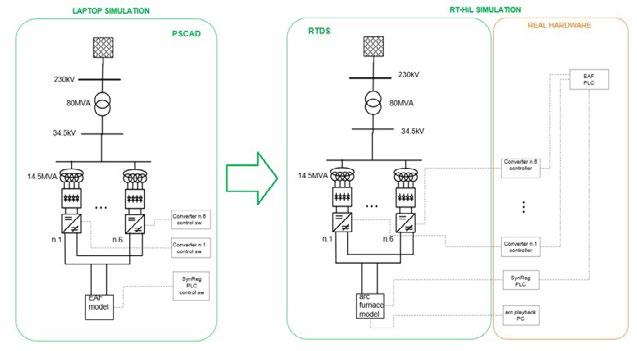
Particularly, the following models are introduced in a laptop environment, adopting PSCAD software for ElectroMagnetic Transient simulation: direct-current arc, high-current busbar system, power converters, transformers and grid equivalent model.
In the laptop environment, the power converter control as well as electrode regulator control are part of the model; instead, in the RT-HiL simulation, real power converter controllers and electrode regulation PLCs are included in the loop, while power system is modelled. In figure 5, there is a principle scheme showing the difference between laptop and RT-HiL simulation: the power of RT calculator is deployed, since power electronics part is running with a smaller simulation time-step than the conventional power parts.
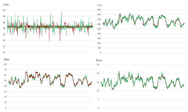
In the graphs below, it shows 5-seconds simulations comparing laptop and RTDS simulations. We can observe red traces for laptop simulations and red traces for RT simu-
lations in the following order: top-left, arc current; topright, arc voltage; bottom-left, medium voltage active power; bottom-right, medium voltage reactive power.
It can be also observed from both simulation environments that power factor is stable above 0.96 level.
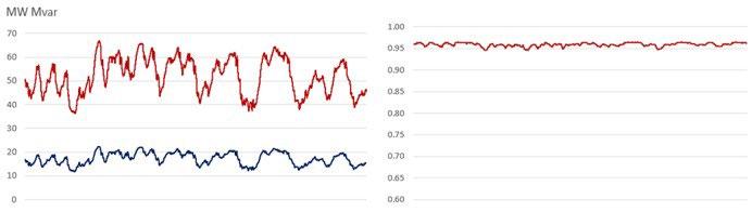
waveforms.
The RT-HiL method allowed us to test and reproduce a perfect digital twin of the system that would be later installed at site. Therefore, it is adopted to verify additional functionalities of AURA system listed below and particularly some of them have been validated with site records. Low-Voltage-Ride-Through. In the case of mains high voltage network, AURA system is running through the voltage sag specified by grid-operator and restriking the Arc furnace once the voltage is established again without tripping or abnormalities.
Fault-Ride-Through. In the case of one of the power converters trips during the heating period, it is online excluded and the system keeps delivering the requested power to the furnace without any downtime.
Hot back-up of redundant controllers. Since every power converter controller is redundant, the hot back-up functionality is first factory tested and then site-tested. Other than power conversion system performances, process benefits were observed during the RT-HiL simulation: especially increase rate of average power transferred to scrap determined to be in the range 10÷15% and consequent reduction of energy consumption in the range of 8÷10%.
EAF hot commissioning planned an arc and burners test before running the first heat at reduced power of 25MW maximum with the purpose of fine tuning of the controllers. Following, a ramp-up to run up to full power of 56MW in just 4 heats, during which all the EAF equipment
was monitored including stoppages to carefully check the status of EAF.
At the end, it took only 3 heats to reach full design power. No further fine tuning of AURA controllers was required, meaning that all parameters set during RT-HiL were correct.
The ramp-up was extraordinarily smooth, in other words a “plug-and-play” power supply. From the first heat to March ’26, almost 3000 heats were performed with no AURA system trip, demonstrating an extremely high availability rate above 99.9%.
Moreover, it was possible to operate the EAF at full power - 56MW - using 5 power converters, demonstrating the robustness of the system with no trips nor thermal alarms occurring.
In few hours from arc-test, we were able to run the EAF at full power production.
The model-based design process is validated 100%, since AURA performances are also matching with simulation. Table 1 below lists a comparison of main performance figures simulated and measured at site.
Tab.1 - Power quality results.
Based on the same network data and short-circuit power, the AURA power supply flicker is compared with a DC-
EAF including SVC, delivering the same power to furnace (table 2).
Tab.2 - Power quality comparison.
AURA DC THY + SVC
The higher control speed of AURA allowed for a faster electrode regulation compared to a tra-ditional DC-EAF type, showing from the beginning in a much more stable power transfer to scrap. Thus, from process point of view,
the increase of power transferred to the furnace during RT-HiL, is confirmed during the observation period at site (table 3).
Tab.3 - Process performances.
AURA technology paves the way for new control strategies which are also part of the development route. Improved control algorithms are under testing and will follow the same validation process, thanks to the de-veloped RT digital twin. SMS is developing in further the AURA power converter design in the direction of increasing the power density and increasing the installation flexibility, to be more effective in green and brown field installations. In the next months, SMS is close to commissioning phase of n.2 DC-EAF 180 tons each in North Europe including
AURA system power supply. For this project, the connection grid-code foresees to provide validated EMT and RMS models: especially, validation is performed thanks to RTDS platform. Other than traditional power quality figures, LVRT and extended frequency temporary deviations are proven.
X-Pact® AURA technology demonstrates technical benefits in terms of power quality, flexibility and availability. The effectiveness of RT-HiL testing in EAF power supply
has been validated: it delivers highly accurate performance predictions and significantly shortens the commissioning period, creating substantial added value for both the Customer and SMS.
Furthermore, X-Pact® AURA system availability is confirmed to be above 99.9%. Fault-ride-through functionality is a remarkable asset for the final user, granting continuous production even with one or two power units not in operation.
Physical inspection of the equipment for regular maintenance is nil, all the parameters being remotely controlled by the AURA HMI in the control pulpit.
Compared to traditional thyristor power supplies, the superior performance of X-Pact® AURA system for both process and grid make it a true gamechanger in modern EAF technology.
[1] M.G.B. Lugnani, L. Bernardis, D. Beacco, M. Daita. “Latest SMS EAF technologies for safety and green steel production,” ESTAD 2025, Verona, Italy, 2025
P.L. Garmier, D. Basic, C. Baviere, P. Clavier, K. Delsol, N. Lapassat, N. Niberon, C. Sihler, F. Terrien
The expansion of EAF production, alongside with the large-scale deployment of renewable energy sources, has significant impact on network stability and local capacity. Steel producers are facing growing pressure to minimize disruptions to the electrical grid and meet ever increasing utility requirements. To tackle these challenges a novel multilevel converter for the decoupling of EAF operation from the medium voltage grid supply was developed, installed and commissioned in a German steelmaking plant in December 2024. This Direct Feed (DF) Power Supply enables steelmakers to increase both power quality and EAF performances. Key benefits demonstrated during full heat cycle operation in the nominal power range (up to 130 MW) include a flicker reduction factor above 10, EAF operation with individually controlled electrode currents, and related EAF performance and operational flexibility benefits that are highlighted in separate EEC 2026 conference papers [1, 2]. Thanks to the gains in controllability, power quality and EAF performance, five large steelmaking plants have decided to build on this new type of MV MMC DF power supply, the largest one is a 340-metric-ton Consteel EAF that will support the customer’s target to achieve carbon neutrality by 2050.
KEYWORDS: MODULAR MULTILEVEL CONVERTER; MMC; ELECTRICAL ARC FURNACE; EAF; FLICKER REDUCTION; POWER FACTOR; ELECTRODE CURRENTS; ARC STABILITY; DECARBONIZATION.
Historically, utility requirements have been sufficiently satisfied with the use of Static Var Compensators (SVCs) and STACOMs connected in parallel to Electric Arc Furnaces (EAFs), which correct the power factor and reduce harmonics, flicker, and unbalance conditions. In the past decade, dynamically controlled STATCOMs have become “the new normal” solutions for furnace compensation with harmonic reduction of 2x-3x for most harmonic orders and flicker reduction of up to 5x or 6x [3, 4]. To date, STATCOMs have been able to meet the utility requirements for harmonic, flicker, voltage unbalance, and power factors. However, when higher power quality of the EAF is required due to a weaker grid supply, in case of very large EAFs with a nominal power above 300 MVA, or a combination of both, the need to electrically decouple the EAF from the network proves more efficient. The use of a converter connected in series to the EAF achieves higher performances than a parallel connected solution like a STATCOM. By decoupling the EAF operation from the grid supply, a Direct Feed (DF) power supply dras-
Conversion & Storage, France
tically improves the flicker reduction level while maintaining a unity power factor at the EAF MV feeder [5]. The use of a Modular Multilevel Converter (MMC) topology guarantees total compliance with IEEE 519 and very high reliability because of the modular design with n+1 or n+2 redundancy in each converter arm.
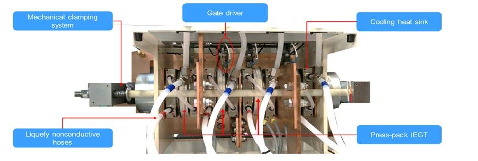
To achieve high robustness and ampacity of the individual power submodules, the DF converter design is based on proven press pack IEGT (PPI) technology that has been used in MV drives for about 20 years [6]. PPIs are pressure-welded high-power devices with built-in IEGT chips. Latest generation Trench devices are used to provide minimum losses and high reliability of the actual switching devices of the converter. Figure 1 shows an example of a press-pack stack with 4 IEGTs. The single IEGTs have a 4.5 kV nominal voltage, with several current ratings available, mainly 750 A, 1500 A, 2000 A and 3000 A. This technology is the base of creating full bridge (FB) and half-bridge
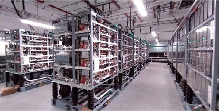
(HB) submodules. The power stacks are cooled by deionized water. Each IEGT benefits from double side cooling. Another benefit of press-pack stacked IEGTs is that the main failure mode is a maintained short circuit, which makes the redundancy implementation easier, and avoids the necessity for arc containment casing. This results in a compact and cost-effective design of the high-power density stacks, converter submodules and towers. A simplified version of the converter-based power supply is shown in figure 2. The EAF and grid side are decoupled by a DC link. The DF rectifier and inverter are both multi-level topologies (n = 16 resp. 24 per arm) to ensure high power quality in the MV networks. Figure 3 shows an installation example of a DF inverter. Each of three inverter arms consists of six HB towers with four power stacks (eight HB submodules) to provide a nominal power of 175 MVA to the furnace at a power factor of 0.75. Additional capacitor banks in the DC link provide additional energy storage and de-coupling between the EAF load and the grid.

The mitigation of arc furnace perturbations provides an extreme load scenario for MV equipment. The main control task challenge is to compensate for the arc furnace impact on the grid during electric arc heating, including the reduction of flicker effects. The (non-regulated) currents from the arc furnace during a heat cycle are very unpredictable (erratic, asymmetric, fast variation). Peak currents during electrode short-circuit conditions can reach values above 100 kA for large directly grid-connected furnaces that are operated without current control. To control the furnace currents and actively compensate the power fluctuations caused by the arc voltage fluctuations, a converter control system with very fast response behavior is required. It is achieved by a distributed control architecture, which reduces the amount of data exchanged with the global control system and optimizes the calculation capacity of the local and global control. The main benefits of the distributed control principle is that sampling periods of the current control loop below 40 µ s are achievable on the inverter side, which is one order of magnitude lower than what is required to control the effective value of the electrode currents to be constant and avoid overshoots of the electrode currents in case of a short-circuit (e.g. if the electrode comes in contact with scrap material). Thus, DF EAF supply systems offer unprecedented performances in the current regulation, which are not possible with a clas-
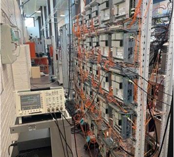
sical MV EAF power supply system, where the externally imposed supply voltage is constant and defined by the tap setting of the EAF transformer. Figure 5 shows a comparison of a full EAF heat cycle that has been simulated in a real-time simulation (RTS) test platform with the actual DF converter control system shown in figure 4 and a furnace model validated by customer site measurements.
The electrode currents are individually controllable in a DF power supply; their effective values can be kept constant during the whole heat cycle. Only in the case that
an arc voltage is required to be above the voltage limit of the DF inverter, the electrode currents may drop to zero. This is explained in more detail below, in section “Generation of Voltage Pulses to Assist EAF Current Zero Crossings”. It is clearly visible with DF operation, there is no more overshoot of electrode currents under short-circuit conditions. It has been confirmed during almost 12 months of routinely operating a large steelmaking EAF with DF power supply that the max. electrode current amplitudes are 30 % lower than with a conventional EAF power supply. A 30 % reduction in peak electrode currents results in more than 50 % reduction in dynamic electromechanical forces, which significantly reduces the stress on the EAF transformer secondary windings and on the entire power supply network, which has a positive effect on equipment lifetime. Other benefits of DF power supplies are:
• independent control of the arc length and electrode current (which is kept constant by the converter);
• the AC/DC/AC converter decouples the EAF from the grid, no reactive power, harmonic and current imbalance can propagate from the EAF to the grid;
• no need for shunt compensation system; no more reactive power peaks on the grid side;
• buffer capacitors in the converter DC link provide partial filtering of active power variations;
• flicker mitigation factors significantly above those achievable with the STATCOM shunt compensation systems (>10);
• variable frequency EAF operation, e.g. 50Hz-60Hz during the perforation phase and 30Hz-40Hz during the refining phase to increase the overall process efficiency;
• increased production through tap-to-tap time reduction (EAF transformer tapping no longer required). These benefits have been demonstrated in a large steelmaking plant in Germany since December 2024 with a DF power supply rated to provide 130 MW of nominal heating power. For customer information protection reasons, no absolute measurement values but only p.u. results can be shown in this paper. The measurements have been reproduced in the RTS platform shown in figure 4, after confirming by site measurements that the EAF load model represents the same operating conditions as the actual furnace, e.g. in using an arc voltage-current characteristic that depends on the EAF thermal state. In cold state of the EAF, the arc is more unstable, and electrode current interruptions may occur, causing unbalanced operation on the EAF side. An example for unstable operation during cold EAF conditions is shown in figure 6.
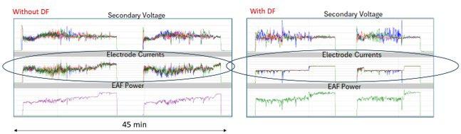
Fig.5 - Comparison of RTS measured values on the secondary side of the EAF transformer during a full EAF heat cycle without (left) and with DF power supply (right).
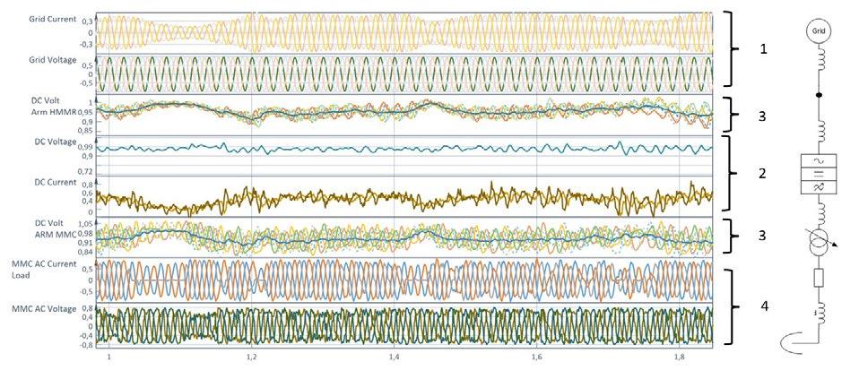
Fig.6 - Currents and voltages on the EAF side (4), in DF converter arms (3), in the DC link (2) and on the grid side (1) during EAF unstable operation with arc interruption.
Around the zero crossing of the electrode current, the arc is extinguished and is regularly re-struck after a certain time during the next half-cycle of the AC voltage, when the voltage with the new polarity has reached a certain value sufficient for arc re-firing. If the arc is not ignited immediately at current zero crossing, the arc current may be interrupted.
It is visible in the MMC AC currents of figure 6 that the single-phase arc interruption causes a temporary drop of the DC link current, whereas the DC link voltage is kept constant, which means that there is a temporary drop of active power supplied to the EAF during such electrode current interruption. On the grid side, the AC currents continue to stay perfectly balanced and the there is no visible effect on the grid voltages, also not at re-ignition of the electrode current or during other electrical transients on the EAF side, because the DC link prevents the propagation of reactive power and the DC capacitors included with each MMC submodule and in the DC link of the converter are able to provide a sufficient filtering of active power transients. In addition, and this is where MMC converters provide a substantial advantage in comparison to two-level or three-level voltage source converters, the multilevel converter generates voltages with an almost ideal sinewave shape on the grid side, thus enabling full IEEE 519 grid code compliance without additional reactive power or filter circuits required. Exemplary values for power quality indices at the dirty bus of a large steelmaking EAF
operated with and without DF power supply are shown in figure 7. For the quantitative evaluation of the flicker reduction factor achievable with DF power supply, site measurements considering all operating conditions must be conducted. Flicker reduction factors above 10 have been confirmed during the final EAF pilot plant performance measurements. DF power supplies take the power quality of electrical arc furnaces to a new level and enable EAF operation in comparably weak grids, e.g. substantially powered by renewable energy sources. They also enable EAFs with nominal power and heat size that exceed the capacity of conventional AC furnaces [7].
Very large EAFs, exceeding the active power that can be provided with a single MMC DF converter with a rated voltage of 33 kV, can either be supplied by an MMC converter design with higher nom. voltage, e.g. 66 kV, or by a parallel connection of two DF converters of the same design as shown in figures 1-3. An example design for a DF power supply that can provide nominal heat power up to 250 MW is shown in figure 8.
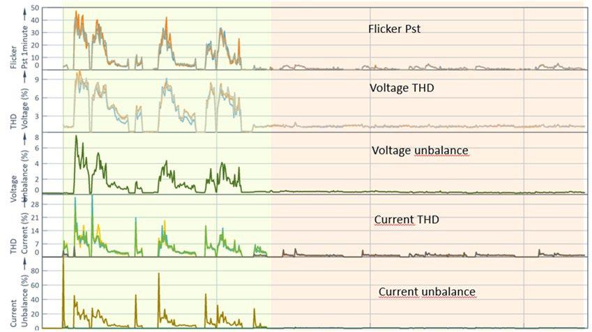
Fig.7 - Comparison of RTS platform measured power quality indices during a full EAF heat cycle without (left) and with DF power supply (right).
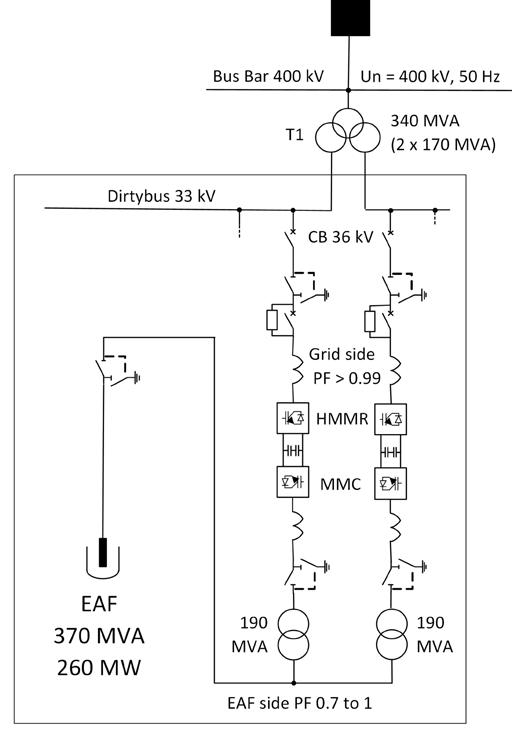
Fig.8 - DF Power Supply for very large EAF.
The larger the furnace, the more important are stable operating regimes. With a DF power supply, the arc length can be varied while the arc current is kept constant, thus enabling new process control strategies [6]. In addition, the furnace can be operated at frequencies other than the grid frequency, e.g. above 60 Hz during the perforation phase and below 40 Hz during the melting phase. While most of these operating regimes have already been successfully tested in the 130 MW DF pilot plant in 2025, the following two sections describe new functionalities that have been successfully demonstrated in simulations with validated model parameters and by measurements on an EAF plant operated with more than 100 MW of heating power - see pages 41 and 42.
In AC EAFs, at the electrode current zero-crossings, the arc temperature drops and the electron density in the arc column diminishes rapidly due to ion-electron recombination. Consequently, electrical conductivity of the plasma channel reduces exponentially. In the EAF cold state, within tens of microseconds, the arc can transit from hot plasma to weakly ionized gas. If the gas is largely deionized, the arc conduction cannot be easily established as
arc reignitions may require nearly full insulation breakdown. Therefore, even with the closed loop current control by a converter supply system, the arc may fail to re-ignite the arc current. It may stay at zero after a zero crossing if the voltage applied by the converter immediately after current zero crossing is not sufficiently high to force reignition/reversal of the arc current with minimum delay before full de-ionization occurs. The voltage is the only physical variable that can restart the arc, while occurrence of the breakdown depends on the electric field strength (applied voltage / gap length), residual ionization and metal vapor concentration. In classical grid supplied EAFs, the EAF voltage follows the grid sinusoidal excitation and adequate voltage at EAF current zero crossings are provided by operating EAF with sufficiently low power factors. This ensures that the EAF current, which is lagging the supply voltage, has zero crossings at sufficiently high grid voltage in the opposite direction, supporting arc current reignition and current polarity reversal with a minimum delay. If the EAF power factor is high, delayed current re-ignitions or even totally missed conduction intervals could occur (arc instability), causing higher voltage flicker and harmonic distortion (including even-order harmonics due to arc current half-wave asymmetries).
To ensure robust arc re-ignitions at the current zero crossings regardless of the circuit fundamental power factor, the converter supplying the EAF can apply short additional voltage pulses prior to the current zero crossings [8]. With such voltage-pulse assisted re-ignition the residual ionization enables almost-instantaneous re-
strike, continuity of the arc and stable power transfer. At the same time the voltage pulses can be short, limited and synchronized with the current (not applied as a bruteforce voltage). Their purpose is just to exploit residual ionization. It is preferable to avoid using square voltage pulses and apply a short voltage ramp instead over a predetermined period (limitation of pulse DV/DT). This helps to encourage volumetric arc ionization, avoid filamentary breakdown, and reduce EMI effects. The EAF current zero crossing instants can be predicted, for example using the controller current reference or using the actual current waveform (for example setting a Phase Locked Loop on the EAF current). The predicted EAF current zero crossing instants can be used as base to define precise timing and shape of the reference for the voltage pulse to assist the EAF zero crossing. Optimal voltage pulse application is at or right after the electrode current zero-crossing, when electron density is reducing but it is still non-zero, and the required breakdown voltage is minimal. However, timing of the pulse voltage reference may be adjusted to consider the control, and the PWM converter delays, so that the instant of the applied voltage pulse is at its optimum. If the additional voltage pulses are applied too late, plasma may already be recombined and the required voltage is sharply increased, resulting in a miss to re-ignite the arc in a smooth way. The applied voltage pulse duration should be adjusted to a sufficient volt-second area, to force a current swing at the reversal up to a value needed to reignite the arc current (holding current):

In the cold start of an EAF, the magnitude of voltage pulses will be relatively higher while in hot state with foamy slag, it will be low (or no pulse voltage assistance is needed). Depending on the available voltage margin, a trade-off between pulse magnitude and pulse duration can be made. The voltage pulse assistance can be readily implemented in the PWM converter control supplying the EAF. Precisely controlled and synchronized application of voltage pulses can advantageously supplement the current control loop of the converter. References of the voltage pulses can be, for example, added to the voltage references synthesized by the current control loop. Due to the relatively short
duration of the voltage pulses the effect on the close loop current control is minimal. It is also possible to temporarily freeze the closed loop current control during application of the voltage pulses. With the voltage pulse assistance, arc reignitions become more deterministic for each half-cycle, and arc plasma continuity is maintained. The final effect is improved arc stability, reduced arc power oscillations and phase imbalances, lower arc current distortion (particularly reduced half wave asymmetry), reduced acoustic noise, reduced voltage spikes at the transformer, and better flicker performance at the PCC. The effect of applying such Assisted Arc Ignition (AAI) voltage pulses at the current zero
crossings has been validated in real-time simulations, as shown in figure 9 and by EAF site measurements, as shown in figures 10,11 and 12. The arc current DI/DT at zero crossings is increased and corresponding improvements in the
arc stability are obtained without the need to operate the EAF at elevated frequencies when it is in cold state. Thus, better system efficiency is expected.
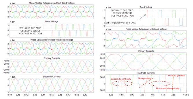
Fig.9 - Increase of electrode current di/dt during zero crossing by injecting additional voltage pulses.
This section presents first experimental field test validation results for the proposed active zero-crossing support of EAF arc currents by means of the assisted arc ignition control (AAI control) method introduced in the previous section. The active zero-crossing support function was implemented in a Medium Voltage (MV) EAF current-con-
trolled converter supply system and evaluated under real high-power scrap EAF operating conditions. All measurements shown in this section were taken during the same operational condition of the furnace, in switching AAI control on and off for a certain period. Prior to activation of the zero-crossing support function, arc current and voltage waveforms were recorded at the transformer secondary side (figure 10).
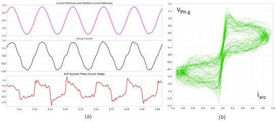
Fig.10 - Measurement results illustrating (a) p.u. arc current i and secondary phase-ground voltage waveforms and (b) dynamic voltage = f(i) plot without assisted arc ignition control Correlations between delayed current zero crossings and high voltage peaks are clearly visible.
The measurements reveal delayed arc-current zero crossings associated with elevated voltage peaks. Under extreme conditions, excessive increases in arc resistance near the current zero crossing can cause the reignition-voltage peaks to escalate rapidly, potentially resulting in sustained arc instability and, ultimately, arc extinction (figure 11).
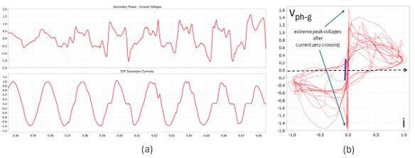
Fig.11 - Measurement results showing the (a) p.u. secondary phase-to-ground voltage and arc current (i) waveforms, together with (b) the dynamic voltage characteristic v = f(i) (b), without assisted arc ignition control. The extreme case shown here is characterized by rapidly increasing reignition-voltage peaks resulting from successive increases in arc-current zero-crossing delays.
After the active zero-crossing support was enabled, delays in the arc current zero crossings were virtually eliminated although EAF was operating in identical operational conditions as in prior case. Consequently, the peaks in the secondary-side phase-to-ground voltages were noticeably reduced at the current zero crossings, together with the distortion of the EAF currents, as shown in figure 12.
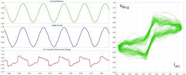
Note: The additional voltage pulses shown in figure 9 were injected at the current zero-crossings. Their effect is not visible in the current reference, but in the actual currents (no discontinuity at current zero-crossings). (a) (b)
Fig.12 - Measurement results (p.u. values) illustrating (a) current reference, actual arc current i and secondary phase-ground voltage waveform and (b) dynamic voltage=f(i) plot with assisted arc ignition control enabled. Smoother current zero crossings and a related reduction of arc voltage peaks is clearly visible.
The obtained preliminary results are in very good agreement with the simulation results presented in the previous section. Furthermore, the results demonstrate that active support of arc current zero crossing by means of the converter-based supply system is feasible under real EAF operating conditions. Additional long-term tests will be carried out to evaluate the impact of the proposed approach on the overall EAF performance.
Due to special requirements for individual control of thermal power delivered by the electrodes, and need for spatial balancing of temperatures within the EAF, options to impose imbalanced electrode currents are desired. EAF electrode current references are typically defined by their rms values. From these values the instantaneous phase
or space vector current references are derived using the space vector concept and d,q and α,β transformations. Further, as the electric arc is a plasma jet with an impulse of force creating movements in the bath, it is of interest to modulate the intensity of this force. By modulation of intensity of the 3-phase electrode currents at a relatively low frequency of 0.1-2 Hz (with appropriate phase shifts of the currents with respect to their geometric positions), a movement in the liquid bath (steering) can be generated, to enhance heat distribution in the molten bath. Thus, the current reference generator is expanded to generate individually settable imbalanced or fluctuating phase current references. Figure 13 shows examples of balanced/ imbalanced and modulated balanced/imbalanced current references (space vector trajectories and phase currents).
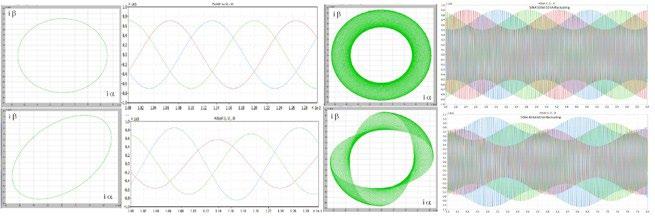
Fig.13 - Space vector trajectories of balanced and imbalanced three phase currents and fluctuating balanced and imbalanced three phase currents.
DF power supplies take the power quality of electrical arc furnaces to a new level and enable EAF operation in comparably weak grids, e.g. grids substantially powered by renewable energy sources. They also enable EAFs with nominal power and heat sizes that exceed the capacity of conventional furnaces. For very large furnaces it is key to assure arc stability not only in hot but also in a cold state
of the furnace. To enable increased arc stability, new converter control algorithms have been developed that do not only enable controlling the amplitudes of the electrode currents to be constant, irrespective of the arc length, but also to avoid current interruption during electrode current zero crossing, thus enabling more stable operation in cold EAF condition.
[1] M. Wurlitzer, M. Safi, “Digital Regulator-Based Control Strategies for Electric Arc Furnace”, Proc. of 14th Europ. Electric Steelmaking conference (EEC 2026), Milano, Italy, June 2026
[2] M. Sanchez et al., “Direct Feed to Enhance Power Quality and EAF Performance”, Proc. EEC 2026, Milano
[3] M. Morati et al., “Industrial 100-MVA EAF Voltage Flicker Mitigation Using VSC Based STATCOM with Improved Performance”, IEEE Trans. on Power Delivery, Vol. 31, no. 6, pp. 2494-2501, 2016
[4] N. Lapassat, P.L. Garmier, F. Terrien, Chr. Sihler, “Multilevel Converter System for Medium Voltage Grids”, PCIM Europe 2023, 09 – 11 May 2023, Nuremberg, ISBN 978-3-8007-6091-6
[5] K. Delsol et al., “New Multi-Level Converter System for Electric Arc Furnace Applications”, AISTech 2024 — Proc. of the Iron & Steel Techn. Conf., 6–9 May 2024, Columbus, Ohio., USA, DOI: 10.33313/388/046
[6] R. Jakob et al., “3-Level High Power Converter with Press Pack IGBT”, Proc. of 2007 European Conference on Power Electronics and Applications, 2007
[7] A. Villa, “Nippon Steel picks Tenova, GE Vernova to supply EAF in decarbonization drive”, S&P Global, online: https://www. spglobal.com/energy/en/news-research/latest-news/metals/020526-nippon-steel-picks-tenova-ge-vernova-to-supply-eaf-indecarbonization-drive, Feb. 2026
[8] D. Basic, P.L. Garmier, C. Sihler, “Method of operating an EAF facility and related electric power supply system”, EP patent pending, March 2026
E. Korhonen, T. Ilmakangas, V. Haavisto, M. Jokinen, P. Huhtala
The Ladle Furnace (LF) serves as a secondary metallurgical process unit for adjusting the composition and temperature of molten steel for casting. Changes and transformations in the steel industry—such as green steel and digitalization— emphasize the need for real-time process control and enabling measurement solutions. This work aimed to study how optical emission spectroscopy (OES) data can be used in process control of ladle furnaces. To this end, data from industrial ladle furnaces was employed to analyze and quantify changes of slag composition and temperature continuously and in real time.
The results show that OES can be used to provide real-time data about the chemical composition of slag and the temperature of slag-steel surface in ladle furnaces and thus allows timely process control. Finally, some special benefits of using OES in steelmaking are discussed. OES can yield information that is not possible or practical to acquire using traditional methods during the process. This cultivates several important use cases and helps operators make accurate decisions.
KEYWORDS: LADLE FURNACE; SLAG; OES; SECONDARY METALLURGY; STEELMAKING; TEMPERATURE.
Secondary steelmaking is where the final steel composition is adjusted. After primary steelmaking, the ladle furnace becomes the control center for refining molten steel, adjusting temperature, chemistry, and purity to meet demanding specifications. Successful secondary metallurgy depends on two critical components: slag and temperature. Both play an important role in the steelmaking process. Controlling these two helps melt shops achieve target steel grades and hit their quality targets. Slag is far more than a byproduct; it is a critical process medium that forms a protective oxide layer over molten steel, shielding the metal from atmospheric contamination. Slag composition determines the efficiency of impurity absorption, the management of thermal conditions, and the control of refractory wear. In the ladle furnace, slag stabilizes temperature for precise alloying, protects steel from re-oxidation and nitrogen pickup, and serves as a sink for unwanted elements such as sulfur and SiO 2, enabling effective chemical refinement. In short: if you
control slag, you control steel quality. In the Ladle Furnace, accurate temperature control is critical to the success of secondary metallurgy. Optimal alloying requires that the molten metal temperature stays within limits. Certain chemical reactions will not happen in too low or too high temperatures. Moreover, too high temperatures may cause equipment wear and further issues in tapping and casting.
The challenge? Slag chemistry is dynamic and complex. Ratios of CaO, SiO2, and Al2O3 continuously shift which calls for continuous monitoring to maintain process efficiency and product consistency. Without real-time insight into slag chemistry, variations can lead to costly inefficiencies and inconsistent steel quality and can impact refractory wear of the furnace lining. Similarly, continuous and real-time temperature measurement is essential for quality management and cost-effectiveness. Measurements enable timely adjustments, improved energy efficiency, reduced heat wear of equipment and thus extending the life of critical components.
The ladle furnace environment is extremely harsh and limits the use of conventional in-situ sensors. As a result, slag composition and temperature measurement is traditionally assessed through probe sampling. This approach
provides delayed and discontinuous process information. Real-time measurements are possible by using contactless and non-consumable technology, Luxmet OES. Technology for slag composition and temperature measurements was implemented in ladle furnaces operated by three European steel producers.
The electric arc in the furnace excites the electrons of the atoms in the slag. The release of this excitation energy generates electromagnetic emissions in the form of photons. These emissions can be observed with a spectrometer, and the measured spectrum can then be processed and analyzed [1].
The system utilizes optical fibers to gather light from a ladle furnace. Measurement heads are placed on the furnace roof, and light is transmitted to a remotely placed spectrometer. In a ladle furnace, Luxmet OES system collects spectrum data, identifies and measures slag components, determines their proportions, and calculates indicator values (such as basicity). The system can measure both the evolution of major slag components and the temperature during the ladle furnace process. The real-time measurement of slag components allows the operator to make needed process control decisions, such as the use of additives, and supports in analyzing the process.
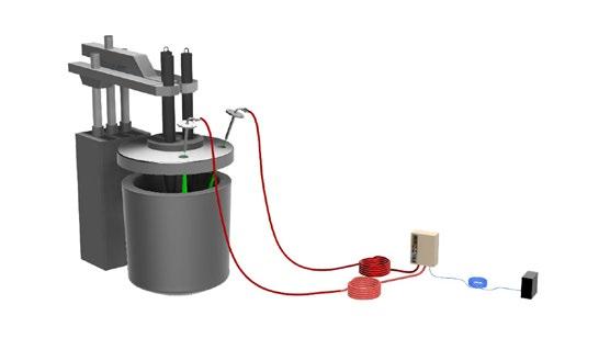
The system can measure the evolution of major slag components during the ladle furnace process. This study focuses on the main slag components CaO, MgO, Al2O3, and SiO2. Each of the major slag components plays a key role
in the process and may have multiple interrelated roles. Even though each slag components have their main purposes, the reality is dynamic. Ratios and relative quantities of each component affect chemistry continuously [2]. The second objective of this study is to evaluate whether the
second measurement head can reliably capture the slag surface temperature in the ladle furnace and providing indicative information about the furnace atmosphere during ladle treatment.
Proportions of slag components can be used to calculate estimations of the basicity of the slag, which is a crucial in-
dicator in the ladle furnace process. Basicity is important for managing viscosity, refractory wear, and slag fluidity. Additionally, optimal basicity facilitates desired chemical reactions, such as desulfurization, and prevents undesired reactions, such as those that are damaging to the furnace lining.
For ladle furnace slag, the basicity is calculated as in Equation 1 [3]:
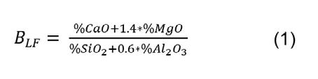
The temperature can be measured from the ladle furnace slag-steel surface. This allows for continuous measurement of temperature changes throughout the heat. Temperature affects how well ladle furnace slag performs. When the temperature is high enough, the slag can react efficiently with the molten steel. If the temperature is too low, the slag becomes less functional, and the refining reactions slow down [4].
A moderate superheat is required for optimal casting conditions. Too high superheat leads to slowing down the process and possible issues. Casting may be interrupted as the cast breaks out or freezes, or there can be surface defects in the cast product. With continuous temperature measurement, the delays and issues can be reduced by optimizing the temperature in ladle furnace [5].
The evolution of major slag components has been measured using the Luxmet OES system in a ladle furnace. A ladle furnace treatment was measured, and the evolution of each major slag component during the treatment is shown in figure 2. The total sum of the slag components does not add up to 100%, as there are other slag components that were not analyzed. The concentration of MgO is rather stable at around 6%. The proportion of SiO2 fluctuates slightly more, especially towards the end. Al2O3 and CaO have stable and fluctuating phases. Midway, aluminum is added to the bath, and the figure shows the change in the component proportions. The relative proportion of aluminum increased, while the proportion of calcium decreased correspondingly.
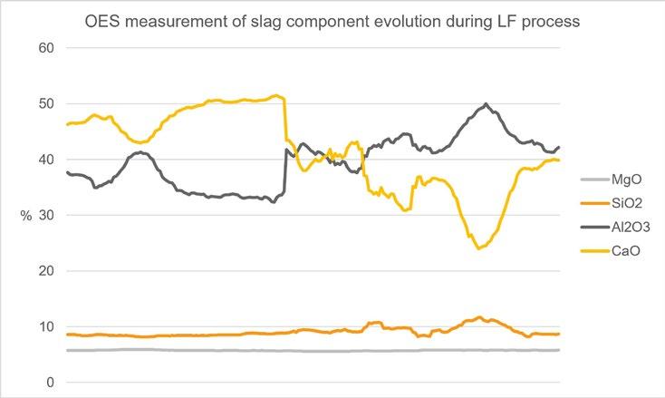
The presented figure of the evolution of components in slag indicates that OES is capable of capturing composition evolution. Changes in components relative proportions can be clearly identified with OES technology, providing reliable information for determining the evolution of these proportions and the effects of alloying on their relative concentrations. OES provides a stable and interpretable figure of the evolution throughout the ladle treatment, making it a suitable tool for monitoring the major slag components.
Figure 3 shows the basicity indicator calculated from the OES measurements as a function of time during the ladle furnace treatment. The continuous orange curve illustrates the evolution of the slag basicity value throughout the process. For comparison, a horizontal grey dashed reference line is included to show the basicity value that was calculated based on an XRF analysis of a sample collected at the end of the treatment. This allows for a direct comparison between the real-time OES based basicity trend and the XRF based basicity of the slag sample at the end.
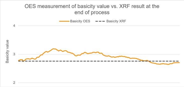
Fig.3 - Basicity values based on OES and the basicity value based on XRF.
The basicity indicator calculated from the OES measurements shows strong applicability for real-time monitoring of slag chemistry in the LF process. The trend follows the expected evolution of basicity and aligns well with the XRF reference value from the end of the treatment. Real-time basicity value information enables improved process control, as operators can adjust flux additions and process controlling actively rather than relying on delayed laboratory analyses. This enhances both the ability to modify the slag toward its target composition more efficiently and the controllability of the refining conditions.
The evolution of temperature has been measured using the Luxmet OES system in a ladle furnace. A ladle furnace
treatment was measured, and the evolution of the surface temperature during the treatment is shown in figure 4. The continuous orange curve illustrates the evolution of the temperature throughout the process. The grey intervals indicate periods which the arc is on in the ladle treatment. The figure shows that accurate temperature measurements have been obtained during periods when the arc is off.
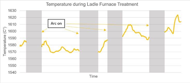
The temperature measured from the ladle furnace using OES technology shows strong capability for real-time temperature monitoring. The trend follows the expected evolution of temperature, and the measurement is accurate when the arc is off. This improves the ability to obtain real-time insight into the furnace conditions during ladle treatment.
Ladle furnaces play a critical role in secondary metallurgy, refining molten steel before casting. While the furnaces offer precise control over temperature and composition, they also present several challenges that can impact steel quality, process efficiency, and equipment longevity. Luxmet OES technology is well-suited for real-time slag analysis and temperature measurement in the ladle
furnace. The OES-based system can provide information on the evolution of slag composition in real time during the process and thus enable timely and precise process control. The evolution of the major components can be measured, and new components are being added to the list. Using a system configuration of two measurement heads, the surface temperature can be measured with the other measurement head when the arc is off, providing real-time insight into the thermal state of the furnace. Real-time, data-driven process monitoring enables dynamic process control. Contactless, continuous, and real-time slag analysis in the ladle furnace can lead to consistent product quality and steel grades, optimal alloying and the use of additives, and the prevention of excessive refractory lining damage.
[1] M. Aula, Optical emission from Electric Arc Furnaces, University of Oulu, Oulu, 2016. ISBN 978-952-62-1092-6
[2] H. Pauna, “Electric arc characterisation and furnace process monitoring with optical emission spectroscopy and image analysis”, University of Oulu, Oulu, 2020. https://urn.fi/URN:ISBN:9789526227313
[3] E. T. Turkdogan, Fundamentals of steelmaking, The Institute of Materials, London, 1996. ISBN 978 1 906540 97 5
[4] M. Andersson et al, “Slag/metal reactions during ladle treatment with focus on desulphurisation”, Ironmaking & Steelmaking, 29, p. 224-232, 2002. DOI:10.1179/030192302225004106
[5] S. Abraham, “On-line superheat control model for continuously cast slabs and billets”, Iron & Steel Technology, 7, p. 89-96, 2010.
Badische Stahl-Engineering GmbH (BSE) is one of the World leading engineering and consulting companies belonging to the Reinforcing Steel Europe B.V. Group (RSE-Group) with its own steel plant Badische Stahlwerke GmbH both located in Kehl/Germany.
Based on over 40 years of engineering and even longer operational experience and competence in the field of EAF-steelmaking, BSE developed its own EAF design with the focus on:
• Robust and reliable equipment
• Compact and easy to maintain components
• Design based on precise calculations and simulations of all parts of the equipment.
• Efficient power input, electrical and chemical
• High degree of automation
• Tools around the EAF for safe and reproducible activities during the EAF process and maintenance.
• Design to meet highest environmental standards
KEYWORDS: EAF STEELMAKING; EAF DESIGN; SAFETY AT EAF; AUTOMATIC FUNCTIONS AT EBT.
Since several years EAF steelmaking is on the rise because CO2 emissions are lower than production via the blast furnace and converter route especially when only scrap is used as charge material. A decision needs to be taken about which EAF technology fits best to the needs for the different kinds of products and raw materials used. For a scrap-charged EAF it is crucial that the dimensions fit the charge material, the electrical power input is adjusted to the shell diameter, and the chemical energy input is supplied correctly to the melt. Correct design leads to an efficient process with optimized performance figures.
All work around the EAF should be automated as much as possible or should be done by manipulators or robots to ensure work safety of the operators. The following paper shows an example of where these features have been implemented together with the results after commissioning.
Ralf Schweikle
Senior Vice President Technical Services, Badische Stahl-Engineering GmbH, Germany
Dr. Jens Apfel
Senior Vice President Head of Sales, Badische Stahl-Engineering GmbH, Germany
Andrea Pezza
EAF Senior Meltshop Process Expert; Badische Stahl-Engineering GmbH, Germany
Only the right ratio of the available volumes of the scrap bucket and the EAF shell with the optimum diameters
and heights of both can lead to fast and efficient charging operation. The volumes of the scrap bucket and the EAF shell are illustrated in figure 1.
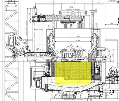
- EAF & scrap bucket section view @ charging.
The given set-up allows 2-bucket-charging-operation with scrap densities down to 550 kg/m3. Scrap falling on the rim of the shell or even beside the shell is avoided with
the chosen bucket- and shell- diameters and will lead to charging times below 1 minute.
- EAF main data.
The EAF is equipped with a 156 MVA transformer featuring electrical power input up to 120 MW. BSE oxygen technology with sidewall and EBT oxy/fuel lance burners with
carbon injections, as well as LM 2 serving the EAF with chemical energy. LM 2 operation enables for oxygen/carbon injection
through the slag door, slag door cleaning by oxygen as well as automatic temperature measurement/sampling during power-on.
The designed EAF for IDC expansion project features a net Tap-to-Tap-Time of less than 41 min. Details of the EAF time balance are shown in the following table.
Tab.2 - EAF Time balance.
EAF TIME BALANCE:
power-on time min 29,3
power-off times, total min 11
• charging min 3
• sampling min 0
• tapping min 3
• tap hole preparation min 1,5
• electrode slipping/re-nippling min 1
• furnace preparation min 0,5
Unexpected delay min 2
Net tap-to-tap, ttt min 40,3
Net productivity / liquid steel t/h 224
To reach such low TTT-time with 2 bucket charge operations, the right set-up of available charging volume in the shell in combination with the set-up of scrap bucket volume is essential.
Another unique feature of the EAF is its gantry design. The gantry design features the following:
• rigid and stiff gantry body which houses the electrode- and roof-lifting system;
• bearing system consisting of 1x axial bearing and 2x radial bearings for accurate and fast movements;
• roof lifting system allows gantry swiveling without roof.
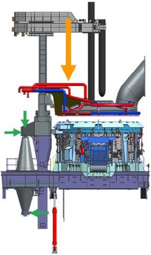
Thanks to the unique bearing system design each bearing can be changed without dismantling of the gantry itself. Nevertheless, the bearings themselves are designed as slide bearings and feature a very long lifetime compared to usually used roller bearings for EAF gantries. In figure 7 the main loads on the EAF gantry and the bearing system are visualized. The orange arrow represents
the total load from the equipment, and the green arrows show the loads on the 3 slide bearings of the system.
The electrical energy input needs to match the size of the EAF shell to avoid high radiation to the side walls. In table 3 the transformer data is summarized.
Tab.3 - EAF transformer data.
Transformer rating
MVA 156
Overload % -
Secondary voltage V 352-1137-1350
Secondary current kA 79,2
Electrode diameter mm 710
Number of taps - 16
Electrical power input, melting/refining up to MW 120 / 110
Following the transformer EAF high current system (HCS), secondary delta closure, high current cables and current conducting electrode arms need to be designed in accordance. A very important design tool is the use of BSE-FNM-simulation for the whole system. With the FNM-simulation [2] the design is optimized to achieve
highest possible “electrical symmetry” of the electrical power input during the operation of the EAF. One of the simulated parameters is the current density distribution in the hole system between transformer connections up to the electrode tips. The outcome of simulation for current density distribution is shown in figure 3.
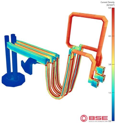
Fig.3 - FNM simulation of EAF-HCS (3D-view of current density).
The chosen design of the HCS can be summarized as follows:
• secondary delta closure in water-cooled copper pipe design with “current-loop” in Phase #2 for triangulation of the hole system;
• 3x 4 water-cooled high current cables;
• BSE-Copper/steel current conducting electrode arms in co-planar design with flanged electrode holders.
For chemical power input the BSE-VLB system was chosen.
The VLB-System is composed of the following units:
• 6x Tiltable VLB mounted in the shell side wall. Each unit with up to 6 MW thermal and up to 2200 Nm3/h oxygen lancing capacity;
• 1x EBT-VLB with up to 4 MW thermal and up to 2200 Nm3/h oxygen lancing capacity;
• 4x CarbJet-lances with carbon injection rate of up to 50 kg/min each;
• LM 2 with 2x oxygen and 1x carbon consumable lances through the slag door.
The layout of the VLB-system is shown in figure 5.
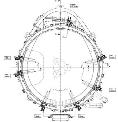
- VLB-system layout (top view).
Thanks to the tiltable design of the sidewall oxy/fuel-lance-burner, shown in figure 5 the thermal power can be up to 6 MW. Depending on the charge mix and operational requirements the control system enables the oper-
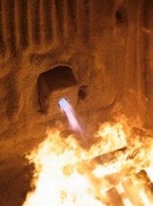
ator to use up to 40 MW chemical energy with this system. The control and power input are executed in automatic mode. Different, pre-programmed operational profiles can be selected depending on the requirements.
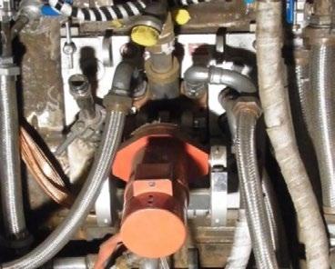
For stable and consecutive EAF operation certain actions and activities need to be executed to ensure productivity and quality. Since these actions have to be executed mainly in danger areas, special safety equipment is required to ensure operator safety and ensure further improvement of overall process performance.
The following examples show technological develop-
ments in the field of automation and safety equipment around the EAF.
The Taphole Manipulator (THM) [3] is a very good example of how an established and proven operational standard can be used to develop a new technological solution for improving operational and working safety.
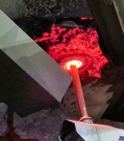
Fig.6 - THM entering taphole for cleaning.
In the past, tap hole breakthroughs frequently occurred caused by remaining slag in the tap hole channel before filled with tap hole refractory. To overcome these frequent breakthroughs with the related delays, the cleaning of the tapping channel with manual oxygen lance in combination with visual inspection before re-filling was set as a standard operation for each heat. As a result, these kinds of operation-delays became practically eliminated at BSW.
On the other hand, the established practice to prevent dangerous process conditions induced frequent manual operator actions in the area of the EBT-balcony panel with “unsafe working conditions”.
Out of this fact, BSE, motivated by BSW, developed the THM for automatic cleaning and clearing of the taphole.
The features of the THM (patented solution) can be summarized as follows:
• oxygen radial nozzle for tap-hole channel and rim
cleaning at the tip of the mandrel;
• force control to avoid damage of the refractory taphole channel;
• max. piece to be removed from top of channel inside the EAF shell is equivalent to ¼ m3 of concrete (650 kg);
• stroke inside EAF-shell is approx. 400 to 500 mm, total stroke of device is 2‘000 or 2’500 mm, depending on layout requirements;
• device can be used for taphole changing.
Figure 7 shows the THM during taphole cleaning at BSW EAF #2. The THM is mounted at the EAF tilting platform. The swiveling is executed by an electric drive, the stroke for clearing & cleaning by hydraulic cylinder. Heat exposed sections, like the lever, are water-cooled for reliable operation.
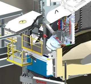
As further part of EAF integrated automation for safety improvement the filling of the EBT tap hole is also already proven in daily operation of EAFs.
Figure 8 shows the EBT filling system in filling position in a section view of an EAF. The filling hopper features a camera for observation of the taphole cleaning by THM and the filling itself. Figure 9 shows the process of cleaning the taphole and refilling.
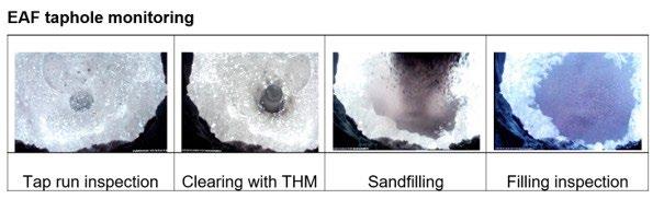
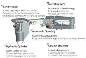
The control of the system is integrated in the EAF Level 1 automation and therefore the residence of an operator in the EBT area for tap hole preparation is eliminated during normal EAF operation.
For supply of the filling hopper with the tap hole filling
refractory a standard pneumatic material conveying system is in use. According to the lifetime of the tap hole, the amount of material for filling is dosed.
EAF slag door with cleaning function
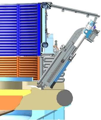
Another system for implementation can be the automatic slag door with the following features:
• reliable opening & closing of slag door during EAF process;
• tunnel & sill cleaning during operation;
• enabling of “closed door operation”;
• safe & reliable operation;
• remote & “automatic” operation.
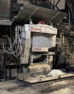
In figure 12 the slag door is shown in charging position. This position shall be used for complete melt down period and close the shell completely.
The BSE-DoorMan [4] is installed at Özkan EAF in Aliaga [5].
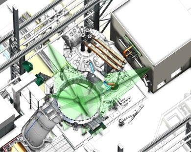
Fig.12 - Visual inspection with three cameras.
With three thermal cameras the complete circumferences of the EAF shell can be monitored. This visual information can give indications on skull build up, steel bath level, possible water leakages and several others. The operators can instantly judge the status of the EAF. With picture recognition tools this information is getting increasingly precise, and estimations of hot heel amount and possible water leakages can be given.
With smart design, automatic procedures through manipulators, visual inspection by special cameras, EAF operation can be optimized for maximum productivity at low cost and high safety level. More tools for further automation of the process will follow in the near future.
[1] R. Schweikle, P. Pfister, H. Acar, A. Tugrul, “BSE-EAF Ready for the Future”, EFRS 2024, Izmir, Turkey.
[2] https://www.bse-kehl.de/de/finite-network-method
[3] European Patent: EP 3 892 947
[4] European Patent: EP 4 177 555
[5] G. Gürler, R. Schweikle, Introducing 1st EAF-Doorman @ ÖZKAN Steel, 7th International Steelmaking Symposium “TODAY. TOMORROW. TOGETHER”, Offenburg, Germany, 20th September 2022
H. Beile
Electric Arc Furnace (EAF) steelmaking plays a central role in the transition toward low-carbon and re-source-efficient steel production. Increasing energy costs, environmental regulations and needed raw mate-rial flexibility demand continuous improvements in energy efficiency and process performance. The operat-ing personnel in steelmaking plants getting younger, more than 10 years in the same profession has be-come rare. Building and maintaining deep-experienced staff as well as achieving highest level of safety is difficult.
This paper outlines key strategies for reducing electrical energy and material consumption in EAF opera-tions through advanced process control, supportive smart-tools, and real-time data utilization. The integra-tion of smart add-ones around the EAF combined with dynamic furnace control systems, including elec-trode regulation, foaming-slag control, and optimized oxygen and carbon injection, enables more stable process conditions, increased safety and lower downtimes.
Raw material flexibility in EAF steelmaking is becoming increasingly important as the availability of high-quality scrap declines and competition for scrap intensifies which makes the entire situation even more dif-ficult. The need to work with ore-based iron units is driven by quality requirements and the demand for cleaner steel. As a result, advanced process control and adaptive operating strategies are essential to maintain productivity, energy efficiency, and final steel quality under more variable raw material conditions.
Well-proven and reliable solutions for EAF process optimization from scrap yard until tapping are presented in this paper.
KEYWORDS: RELIABILITY; EAF PROCESS CONTROL; RAW MATERIAL FLEXIBILITY; DYNAMIC EAF CONTROL; SUPPORTIVE SMART TOOLS.
The steel industry is facing challenges with respect to globalization, decarbonization, raw material availabil-ity or even staying attractive as employer for the younger generation. The main questions are: how will the raw material situation look after most blast furnaces are shut down? Which design features or smart tools around the main equipment are needed to ensure highest flexibilities in raw material usage and highest productivity, with lowest operational costs and highest possible safety for humans? How to ensure that a limitation in workforce and experience does not have a major impact in productivity and safety?
This paper will address and briefly discuss these three
Beile tripleS GmbH & Co. KG, Germany
main topics in each case and give an overview to overcome the challenges:
1. raw material flexibility, to be prepared for most developments;
2. supportive and proven tools around the EAF to increase safety and lower costs;
3. how to overcome constraints in experience and maintaining experience.
Most forecasts show a difficult future regarding scrap availability with useful quality and density, especially after most integrated plants transformed to Electric Arc Furnace operation which will lead to an overall in-creased scrap usage. An increased number of scrap buckets per heat, due to low scrap density and/or a higher percentage of ore-based material usage to overcome trace elements due to lower scrap quality, will force steel mills in future
to either substitute scrap with other materials or to invest in one own scrap pro-cessing equipment.
Ore-based material usage in an EAF
Steel plants which were producing advanced steel grades based on 100% scrap in the past will most prob-ably be using ore-based material in future to keep qualities and cleanliness as it was. Former integrated plants who want to keep their advanced steel grade qualities as well with their new EAF-production route have to use up to 40% ore-based material like PI, DRI or HBI; maybe even more. Not all ore-based raw materials could be charged in unlimited quantities with the scrap bucket, not all mate-rials could be used in combination without negative influences on each other and, finally, an increased us-age of DRI or HBI will lead to decreased productivity and increased operational costs, especially if the EAF is not designed for such a usage.
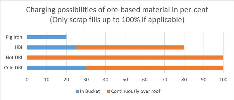
Figure 1 shows the different possibilities of using orebased material in an EAF. Pig iron, if not granulated, could physically not be charged continuously over roof because it is too heavy for bins and belts. A theoretical process of 100% HBI would be possible, but this will end up with a negative impact on productivity, energy and refractory. The size of the briquettes itself, mostly the chemical composition and therefore the entire melting behavior does not allow a profitable HBI usage of 100%. Globally no well-known steel-plant is constantly using HBI above 50% for a reason. Cold-DRI as well as Hot-DRI could be fed continuously over the roof up to 100%. Main operational costs for the EAF in between 100% scrap operation
with a standard quality and 100% Hot-DRI through the roof based on standard quality is nearly equal. DRI charged within the scrap buckets has its limitations because this dense material is creating icebergs which are hard to melt. For an efficient melting process such heavy and dense material needs to be charged low in the bucket to have a quick contact to the liquid heel. Having the possibility of using Hot-DRI is rare and if so, it would make no sense to charge a limited amount of Hot-DRI within the scrap bucket and lose all the benefit of increased temperature, therefore this version is not shown in figure 1. The percentages of DRI or HBI charged within the scrap bucket could vary, based on amount of hot heel or num-
ber of scrap buckets charged per heat for example. If we combine the usage of different ore-based materials within one heat, the process tuning is even more difficult. 50% scrap usage together with 40% HBI continuously over the roof and 10% PI in the scrap bucket as example: The PI will keep the steel temperature longer on a cold level and the carbon out of the PI is very late available in the melt (>1580 °C). It is essential to find the correct raw material scenario to ensure the needed steel quality on lowest possible price base which is at the same time the most OPEX (operational cost) friendly process for the EAF.
The EAF design itself plays an important role to be efficient for specific raw material scenarios. As easy example let us compare the upper shell for an EAF with mainly scrap operation versus an EAF which is designed for DRI
melting. The scrap furnace generally has a higher upper shell to create more volume. Target generally is to reduce the number of scrap buckets as much as possible per heat. One charging cycle/roof opening costs around 10 kWh/t of steel on energy losses. A DRI upper shell on the other hand does not need any volume for charging; therefore, DRI furnaces normally have low upper shells which create several benefits. Main benefit is a reduced water-cooled surface which ensure lower heat losses to the cooling water. Another benefit is the entire electrode handling because a shorter stroke ends in a more stable and reactive regulation.
Different scenarios need different design solutions to ensure most efficient process conditions, but what happens if an all-in-one solution is needed because flexibility is one of the main criteria? Following, figure 2 provides an overview over technical design adaptions to ensure a high raw material flexibility as well as efficiency using an EAF.
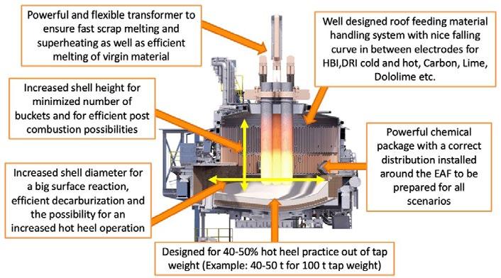
More and more supporting tools around the EAF are meanwhile state-of-the-art in many steel plants. The philosophy of zero-man-on-the floor with safety fences around hazard zones should help to reduce accidents down to zero.
Which supporting tools around the EAF are existing and how proven and reliable are they?
Advanced slag door to clean the slag tunnel and maybe
even push the scrap inside the EAF during operation
Nearly all equipment suppliers have at least one solution for a new generation of EAF-slag-door. In the standard design the slag door is lifted by a chain and lowered due its own weight. If slag is accumulated in the tunnel, it will not be possible anymore to fully close the door. New generations are equipped with hydraulic cylinders to be able to lower the door completely and to control the opening rate to create a controlled slag flow. Most of these slag doors have the possibility for cleaning the tunnel and push or,
even better, pull the slag with a horizontal movement. Using a forklift for slag door cleaning and scrap pushing is not common anymore and in quite some plants already forbidden. Some of those new door design installations
are heavy, additional hydraulic close to the EAF is not really welcome due to additional possible safety issues; such complex equipment with additional cooling water usage and increased maintenance effort are as well.
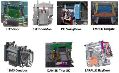
On the other hand, such new slag doors helping to avoid close contact to the EAF during operation and therefore it will increase the safety level combined with a controlled slag flow. An external door pusher which could be moved away from the EAF slag door (mainly by rail-tracks), and therefore away from heat and radiation in combination with an advanced slag door—just for having the opportunity to close the door and control foaming slag flow— could be a good alternative for achieving the same safety level with a higher flexibility and higher availability.
Offgas measurement devices for safety and process control
The energy losses to the furnace offgas play a major role in the energy balance of an EAF. These losses can be re-
duced by using dynamic process models in combination with real-time offgas monitoring, which together are controlling the process in a closed loop by closing the mass balance over carbon using the CO and CO2 readings, together with the offgas temperature and speed/flow at the exact same spot before the offgas post-combustion starts. With the same offgas monitoring system including a water sensor, the mass balance can be closed together with an increased safety level. Leakages in the roof, sidewall or burner panels could be indicated by such sensors.
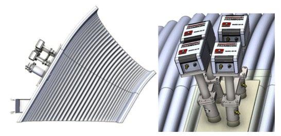
A modern offgas sensor based on Infra-Red technology is shown in figure 4, which provides real-time read-ings without any lances going in the offgas duct and requiring little installation and maintenance efforts. Equipment availability is unbeatable since there is no installation inside the duct. What is still insufficiently done—regardless of system or supplier—is the integration into the EAF process control system. Real cor-rections, interventions or at least pop-up windows with alarming due to the offgas readings are not done so far.
Manipulators or robots around tap-hole area as well as for temperature and sampling
Probably the most common and well-known areas for
supporting tools nowadays are the temperature and sampling robots or manipulators. Temperature measurement and samples must be taken regularly and in most cases through the slag door. Fully automated robots can do these jobs including change of cartridges, sending these samples as well to laboratory is not yet often observed in real working order.
As second possibility—with a manipulator—whereas the most dangerous job is done by the tool, but one person around the slag door area is still needed to change cartridges and prepare the probes.
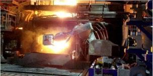
- Fully automated EAF T+P robot (temperature
Today most of the jobs around the taphole are still done manually in steel plants. If the furnace had an un-foreseen delay, or the EBT-filling was not done correctly, a nonfree-opening can happen, and it is neces-sary to open the taphole with an oxygen lance. This could be a very hard and dangerous job but depending on access it gets complicated quickly. Manipulators for an automatic or at least semi-automatic oxygen blowing can support in this respect and in most cases, it saves time as well. The other problem can be a blocked taphole with unmolten pieces, which are “rolling” into the taphole during tapping and this needs to be removed before taphole filling. Taphole pusher systems have been developed to sup-
port here. Both systems—the oxygen lance as well as the pusher—are important tools to ensure an increased safety around the EAF during operation and in-between the heats and they are available nowa-days from most suppliers. Since these tools are mounted directly at the EAF lower shell it is ensured, that the lance or the pusher hits the taphole correctly regardless of furnace angle. Changing oxygen lances, adding ignition support on these lances or tracking the lances during oxygen blowing with the correct pres-sure is the challenge here. These are mostly the reasons why solutions mentioned tend to take more time compared to doing it manually even if it works mechanically unrestricted.

The tap hole pusher itself is generally easier. No consumable components, no ignition needed and so on. Finding and adjusting the correct force of pressing is the key here. If some unmolten parts really stuck in-side the taphole and the pusher is using a lot of force a possible worst-case scenario will be pushing the taphole bricks entirely inside the EAF.
Taphole filling and observation to see if the taphole is free and clean can also be done fully automated from the pulpit as shown in figure 7. This application is getting more popular as there are reliable and fast solu-tions available. Steelmakers see this as one of the best developments with respect to safety and productiv-ity as in several plants, turn-around times have been cut down to lower than 45 seconds only.
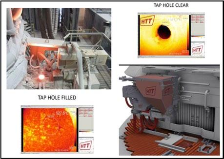
Electrode handling
With tools like shown in figure 8, the number of electrode breakages can be reduced as there is no risk an-ymore of too low or excessive torque and/or damaged nipples. If the electrodes are connected piece by piece from top it is working like an endless electrode and less entire electrode changes are needed. The thermal shock by bringing
a new electrode column to the EAF with a cold tip is therefore reduced and the used piece is not oxidizing in the storage stand, which results in a lower overall consumption and tip loss-es. Furthermore, no person is needed on the EAF roof anymore to guide the crane driver and check the connections.

- Electrode handling and jointing [6].
Humidity sensor behind refractory
Every now and then, steelmakers are reporting about serious breakouts in lower shell of the EAF due to water accumulating behind the bricks coming from small leakages, where the water is not directly evapo-rated. This can happen, when the EAF is stopped, and the furnace roof
is closed for example or if a leakage is directly facing the refractory gap or if the safe version of shell cooling is used (pressureless spray cool-ing). This water is destroying the refractory material or is pushing the bricks inside the furnace when heat-ed up and so leaving gaps, where the steel/slag can cut the lower shell plate.
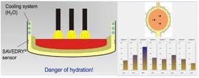
When humidity accumulates behind the bricks, an alarm is created warning the operator. Often in these cases, leakages are detected in a following check of the furnace.
Pressureless cooling – safety and costs
The spray cooling is more than just a supportive EAF tool. As long as safety is the main concern, this topic simply cannot be omitted. If a water-leakage occurs, which can never be fully avoided in a melting or refin-ing unit, the
amount of water which enters the EAF is significantly lower with < 0,1% compared to a pres-surized tubular cooling system, where the water has around 4-5 bar in the water-cooled panels itself.
Furthermore, maintenance efforts and spare part cost are less compared to tubular cooling especially if due to a high refractory-wear-index copper is needed, which could be avoided by placing the nozzles correctly and with different flows with the spray-cooled system.
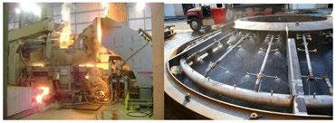
The overall amount of cooling water is normally reduced, but maximum the same compared to tubular de-sign. Finally, there is a higher equipment availability as with a small water leak, the EAF has not to be stopped due to a limited risk of accidents, and also a simple patch could be welded from the cold outside within 20-30 minutes in case of a larger leak instead of changing panels that is dangerous and may take hours.
Consistency and reproducible operation as much as possible in respect to product variety and raw material changes is one of the main keys to ensure highest productivity in combination with lowest operational costs. A stable and constant amount of hot heel is very important to achieve
these goals. Another point where long-term expertise is needed to be able to judge correctly the amount of real hot heel (without re-maining amount of slag). Cameras, laser or radars are just able to measure distances which ends up in in-accurate results from the entire input (steel and slag) without even knowing actual bottom shape (ramming material shape). The real amount of liquid steel remained unknown. A new tool is now able to calculate the real amount of liquid steel remaining after tapping due to weight differences and resulting movements of the furnace during tilting.
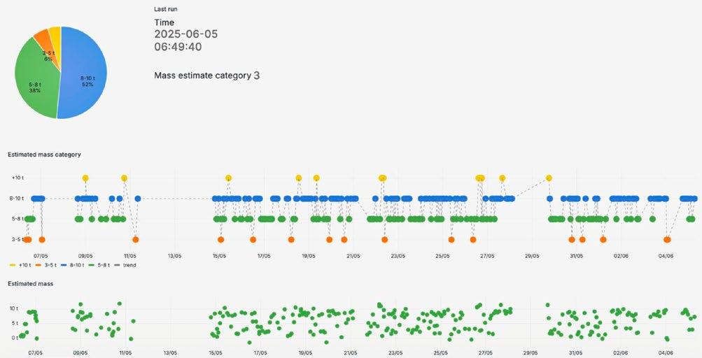
Fig.11 - HMI screenshot of hot heel measurement results.
How to combine all this additional information and how to implement the supportive tools
All mentioned supportive tools in this chapter, all measured values and process data from and around the EAF, can be processed in the new generation dynamic process
models to adapt online the working profiles with the consequence to improve the overall efficiency of the EAF. With a control architecture as per figure 11 for example, savings in conversion cost as well as a production increase can be theoretically achieved.
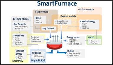
Fig.12 - Possible structure of modern EAF control [9].
This will be the future, and this will be the way to really achieve “Industry 4.0” standards and something like “zero man on the floor”. These ideas and these advertisements have existed for years, but the reality still looks different. Holistically such a fully automated interlocking structure
is simply not yet running or achieved. Where is the Electric Arc Furnace in operation, where for example above average CO emissions measured during scrap melting is automatically treated by changing slightly injector setpoints to be more over stochiometric to support post combustion
in the shell? Where is the EAF in operation where continuous slag analysis lead to a system self-adjustment of CaO, MgO or carbon adding during the process or simply improving foaming slag?
Once again: this should be and this will be the future, now the reality shows that we are not there yet. The previously mentioned tools around the EAF already help to get more information and to avoid having people working in hazard zones, which is an important step, but the journey is not over.
This is probably the most important and the most difficult topic and, at the same time, a priority all over the world. One point right from the beginning: there will be no straight answer, there is no single solution which always helps. Just a few points that could help to push the development into the right direction.
To understand actual upcoming problems or challenges, first in many plants must be understood the development
and the change of people, including their way of thinking. Working behavior has changed quite a lot over the past 10-20 years, especially when you compare older generations with younger ones.
This is less about “better vs worse” and more about different priorities shaped by technology, economy, and culture. The main issue is this shift of “working attitude” which a steel plant, that is mostly located outside cities and far away from interesting “hot spots”, operating 24/7 in a severe, dirty and hot environment not really offer. Work is nowadays just a part of life and there is no duty or identity anymore. Personal fulfilment matters more than stability. Strong emphasis on long-term security and staying at one company 30 years or more was normal in the past. Today job-hopping every two to five years is normal, where fast growth and flexibility is priority. This comes primarily at the expense of experience. Fixed working hours and, of course, working shifts as well during weekend, with a strict hierarchy and understandably “presence at work”, was status quo and standard versus remote work and flexible hours.

What hurts the most in first place is finding young people who are willing to work and learn in a steel plant and at best for more than 5 years. Steelmaking, especially if many different high-quality products are pro-duced, is a manufacturing industry which cannot be learned or fully understood after 3 years of working. Digitalization is not yet that developed in the steel industry (like mentioned in the chapter before) and, even if it were, a well-trained and knowledgeable person is always needed in the background to intervene or to react quickly and correctly in case of failure.
A very high level of automatization and digitalization is needed in future to overcome some of these prob-lems and at the same time it is essential that people do from time to time these “automated” jobs manually to learn how it is done. This “manual” knowledge and understanding of the process and the equipment is the base of being able to keep the production alive if certain mechanisms or automatisms failing and it is the base the gain a higher knowledge and confidence level to make correct decisions in critical situations. That is a balancing act which is very difficult to handle. Another example: some plants
have already blocked the opportunity to manually interfere or adjust chemical and electrical setpoints if certain circumstances are changing. This will lead to a situation in future where operators, even if some are willing and know how to, are not able to adapt the process in a more efficient and safe way because the allowance is gone. A real understanding of processes and equipment from the people working on-site every single day will increase availability and decrease unforeseen delays.
A major target for the upcoming years should be the introduction of another level of automatization and digi-talization in combination with constant training and support
of operators and maintenance. Flexible working hours and remote work is with above mentioned points still not realized but a situation is created where constant work (manual training sessions for example excluded) in severe conditions are minimized. Knowledge and deep expertise of workers participating in production and maintenance is one of the three pillars for business success. A human’s willingness to contribute more and taking ownership increases if this human feels more as part of the “journey” and being involved in companies development instead of be-ing just “employee”.
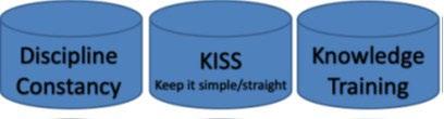
A major steel manufacturer in the US has implemented a bonus payment system which is as well creating some additional incentives. If the productivity is above defined target the employees receiving additional bonus which creates on top a feeling of being more honored in the entire business success and workers support each other beyond departments and core-equipment. The importance of workers with their knowledge should not be neglected: this is the foundation of a suc-cessful cost-efficient steel production.
Electric Arc Furnaces are very flexible in terms of raw material input, but some design features should be followed to combine this flexibility with the greatest possible efficiency. The integrated plants who will soon convert to electric steelmaking already studied their possibilities in raw material input and their most effi-cient way to keep their portfolio. Existing electric steelplants understand increasingly that an invest in scrap yard and own scrap cleaning as well as processing equipment together with an upgrade inside the melt shop—implementation of bins and belts for roof feeding or a modified lower shell to car-
ry a bigger hot heel as example—could be beneficial upgrades in future.
Safety and efficiency play a key role in modern steel plant operation to be competitive on the market as well as being attractive for new operators or engineers to work in a challenging environment. Technologies, which are satisfying both aspects, have been developed and are meanwhile state-of-the-art with acceptable availability and accuracy. After all, workers are still the key. They are operating and maintaining the equip-ment, which can either produce in the most efficient way, quickly reacting to changing circumstances with a shop pacing and melt shop organization that ensures a most beneficial production based on knowledge and experience, or it could end up differently.
[1] 3D section view of an EAF by Primetals (picture only)
[2] Different slag-door concepts from homepage of every OEM (Danieli, BSE, HTT, SMS, Saralle, INTECO, EMPCO)
[3] Equipment presentation from PROMECON
[4] Product presentation Polytec/BM group
[5] Product presentation HTT engineering
[6] Product presentation Piccardi
[7] Equipment information SAVEWAY
[8] Equipment information Systems Spray-Cooled Inc
[9] Product presentation AMI automation
[10] https://www.tonerbuzz.com/blog/worklife-balance-statistics/?srsltid=AfmBOopCfTpn_h18-aesonJahXCteBAnnFBv3LZpW0wLudI 2khB7Xw1p
P. Marterer, P. Shikhmetoff
A leading company in Middle East (C.M.E.) commissioned an automatic sealing slag door (SwingDoor™) system without door burner supplied by INTECO PTI on an Electric Arc Furnace (EAF), operating with approximately 80 % cold
Direct Reduced Iron (DRI). This installation represents one of the first industrial applications of automated sealed slag door technology in a DRI-dominant furnace, whereas prior global references were primarily scrap-based. The project aimed to enable closed-door melting practice, improve slag retention and reduce air ingress. Initial commissioning identified several operational and design constraints which were resolved by subsequent engineering modifications. Following operational stabilization, validation during the Performance Guarantee Test (PGT) confirmed measurable improvements, which were determined to be even better than previously calculated, in:
• Electrical energy reduction
• Electrode consumption reduction
• Metallic yield increase
• Flux consumption reduction
• Slag generation reduction
This paper documents installation constraints, commissioning learnings, operational performance, and future enhancement opportunities including slag level prediction and automated de-slagging optimization.
KEYWORDS: SWINGDOORTM; SLAGDOOR; ELECTRIC ARC FURNACE (EAF); CLOSED-DOOR OPERATION; SLAG MANAGEMENT & RETENTION; DIRECT REDUCED IRON (DRI); ENERGY & EKECTRODE CONSUMPTION REDUCTION; AUTOMATED DE-SLAGGING.
Electric Arc Furnace steelmaking is undergoing structural transformation driven by decarbonization, scrap scarcity, and increasing utilization of alternative iron sources such as DRI and HBI.
High-DRI operations introduce unique slag management challenges, especially low DRI/HBI grade with higher gangue content, increased slag volumes, lower yield and more iron losses during de-slagging process.
One basic limitation of the conventional slag door lies in its poor control of de-slagging especially with higher slag volumes. Consequently, there is always a risk of metal seeping through the “V” channels formed on the slag door breast.
DESCRIPTION OF THE CHALLENGE
In DRI based EAFs, the generated slag quantities are
INTECO PTI s.r.o, 591 01 Ždár nad Sázavou, Czech Republic
INTECO PTI Inc., 4950 Royal Atlanta Drive #A, Georgia, USA, 30084
higher compared to scrap-based furnaces due to high DRI gangue content and the need to provide enough flux to neutralize the acidic content. Typically, DRI with higher gangue content requires bigger quantities of basic fluxes. Due to the large volume of slag generated, it is continuously discharged through the slag door tunnel—via a partially open conventional slag door—throughout the heat.
This continuous flow ensures that the slag door tunnel remains free of scrap and cold slag. As the door is permanently open, energy is lost and DRIfines are partly lost through the continuous de-slagging as well resulting in loss of metallic iron through slag discharge and lower yield.
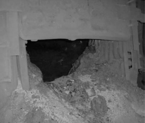
In order to increase the overall furnace efficiency C.M.E., one of the leading companies in the Middle East in 2024, aimed to change the above described open slag door to closed-door melting practice in one of their EAFs with a capacity of 110t/heat and 1.1MT/Y capacity, which is charged with ~ 80-85% cold DRI (CDRI).
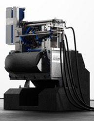
C.M.E. estimated that the closed-door operation will increase the furnace efficiency by the ability to retain slag and reduce air ingress. At the same time, it should increase operator safety. After validation of available technologies on the market, the INTECO PTI SwingDoorTM was figured out as the most suitable one.
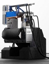
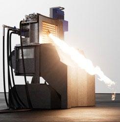
INTECO PTI reviewed the current operational performance of the existing furnace at C.M.E. and calculated the following expected measurable improvements from the installation of the SwingDoorTM:

• electrical energy reduction ≥ 6,5 kWh/t;
• electrode consumption reduction ≥ 0,025 kg/t;
• metallic yield increase ≥ 0,8 %;
• flux consumption reduction ≥ 1,4 kg/t;
• slag generation reduction ≥ 10 kg/t;
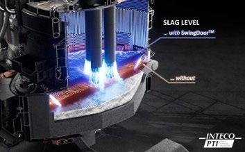
The INTECO PTI SwingDoorTM is designed for modern EAF operation to better control the de-slagging process. The system is specifically designed to allow the EAF to be operated with a closed slag door which notably improves operational efficiency. The main operational function of this device is to control the amount of slag and increase the slag retention time inside the furnace which enhances
the arc stability and improves the yield of raw material and fluxes. The SwingDoorTM is mounted on the upper shell in-line with the other water-cooled panels to eliminate the need for the slag door tunnel and therefore, prevents semi-molten scrap/slag from accumulating on the furnace breast. The SwingDoorTM has a flexible design which can fit with scrap based as well as DRI based furnaces.

Depending on the percentage of scrap charged to the furnace, the SwingDoorTM can be equipped with an integrated burner that operates through the door in conjunction with the other sidewall burners. The door burner melts scrap in the door area eliminating the boiling effect from the cold refractory area in front of the door before it is opened for temperature sampling. In scrap-based furnaces, a burner is mounted onto the SwingDoorTM . The SwingDoorTM designed for 100% DRI based furnaces, with a low percentage of charged scrap, is not implying a slag door burner (flat bath operations).
The main design change needed to the slag door area of the EAF to install the SwingDoor TM solution is the elimination of the slag door tunnel. To accomplish the removal of the tunnel, the slag door is repositioned in-line with the other water-cooled panels of the upper shell. The refractory around the slag door area is modified to ensure that slag moves smoothly from the furnace into the slag pit or slag pot. Even though the slag door is repositioned dramatically, the existing upper and lower shell designs are kept virtually intact. For the upper shell, a specially designed frame is welded to the structure that allows the SwingDoorTM to attach to the EAF upper shell.
The compact design of the SwingDoorTM ensures smooth operation of existing manipulators and robots (e.g. for automatic temperature and sampling).
The door is designed to have a gap between the tunnel bottom bricks and the door bottom with closed condition. The gap is essential to ensure smooth door movement and avoid door being stuck. The height of the gap depends strongly on the slag composition and differs between scrap-charged and DRI-charged furnaces.
Hydraulics are typically easily adapted from the current furnace hydraulic system. It is recommended that 160 bar are maintained for good operation. PTI has developed a new actuator system that is currently offered for the SwingDoorTM which can be used up to 210 bar.
All components of the SwingDoor™ are engineered to ensure maximum ease of maintenance and operational safety. High-wear parts are secured with pins rather than bolts or welds, enabling fast and straightforward replacement. All utility connections are located at the top of the door, keeping hoses away from heat exposure and other hazards typical of the EAF environment. A complete SwingDoorTM assembly can typically be exchanged with a spare unit within a standard maintenance shift.
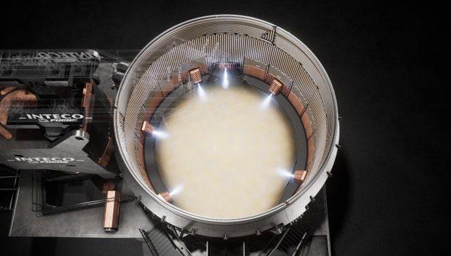
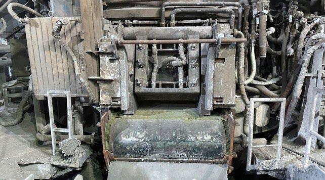
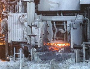
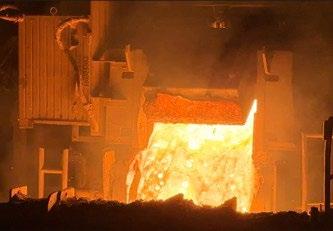
In this chapter the challenges faced during the commissioning of the SwingDoorTM followed by the measures that solved the challenges are described.
Unlike ideal installations, structural constraints of the existing furnace at C.M.E. limited upper shell modification and required the door installed offset from shell panel line which promoted slag and scrap accumulation at the door interface, potentially affecting closure performance.
“IDEAL” reference installation
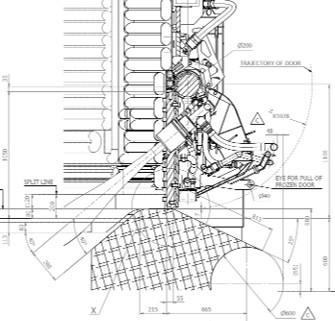
To eliminate potential closure performance issues, the entire operation of the SwingDoorTM got fully automated and integrated into the furnace PLC, with all movements described below requiring no operator intervention. During melting, the door remains closed. After a predefined energy input, the door opens for the first de-slagging. The timing of the 1st de-slagging is highly dependent on rate of slag generation inside the EF (DRI/scrap gangue content).
The first de-slagging is at a power consumption of approx. 35-38 MWh, and the last opening at a power consumption of approx. 46-48 MWh just before tapping for sampling and temperature measurements (see figure 9). In conventional scrap-based furnaces, this intermediate
C.M.E. installation
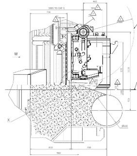
de-slagging is generally unnecessary due to the lower slag volume. In the C.M.E. process, however, it is required to prevent foaming slag from escaping through the EBT panel opening.
Operator stops feeding lime and DRI when the door is open to further improve material yield and reduce losses through slag.
Shortly before tapping, the door is opened again for the final de-slagging operation. This multi-stage de-slagging improves slag residence time and flux utilization. During tapping, the door remains closed and is opened to approximately 40° shortly before the rapid back-tilting movement in order to ensure that no steel from the hot heel comes into contact with the door plate.
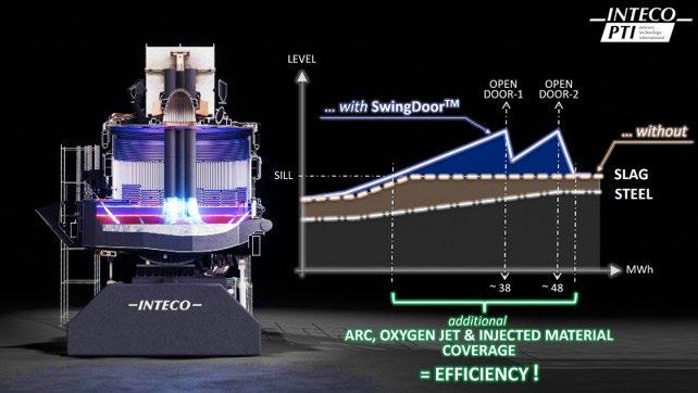
After tapping, the SwingDoorTM is opened to about a 120° angle to allow the operators to inspect the furnace refractory and, if needed, clean residual slag from the door area and prepare for the next heat. During charging, the SwingDoorTM is closed to -8° angle to avoid slag accumulation in front of the door and in the tunnel during scrap charging.
An automatic movement to -8° and back to 0° is also integrated to ensure that any slag accumulated directly in front of the door is loosened and removed during the subsequent de-slagging cycle.
Operational experience confirmed that slag chemistry
significantly influences door sealing performance. If the slag is too liquid and the level of slag inside the furnace becomes too high, leakages between the lower edge of the door and the breast could occur.
In early operation, supplementary magnesia clinker addition was required at the breast to enhance sealing until slag chemistry stabilization was achieved.
C.M.E. adjusted a higher slag basicity (approx. 1.7 – 1.8) which led to following improvements:
• slag cohesion;
• sealing integrity;
• leakage resistance.
A linear transducer inside the hydraulic actuator was developed during the C.M.E. project (impeded inside the cylinder hydraulic oil) to measure the door opening angle. Initial design placed the linear transducer inside the hydraulic cylinder (cooled down by hydraulic oil) which showed frequent failures due to elevated hydraulic oil temperature.
The radiant heat from slag door zone was the main reason for the elevated temperature of the stagnant hydraulic oil leading to damage the linear transducer.
This configuration proved unsuitable for high-DRI slag operations.
During the 2nd trial, the transducer was relocated and externally mounted on the cylinder body as well as thermally isolated from the hydraulic oil.
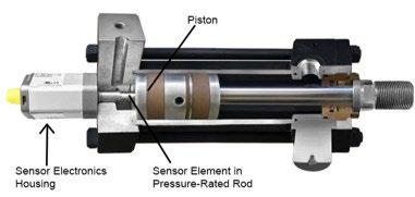
During the initial trials, C.M.E. observed a water leakage in the lower part of the door plate due to inefficient water cooling for this part.
The circuit was successfully modified during the 2nd trial, and water leakage has been eliminated by:
• optimized inlet distribution;
• improved hose routing.
Thus, leakage frequency was reduced to negligible levels.
The most difficult issue at start-up was the learning curve of how to maintain the breast. The door provided effective sealing performance; however, due to C.M.E. specific door installation not in-line with the water-cooled panel and the long, straight breast area allowing slag accumulation, complete closure was not achieved during initial operation, as the door was obstructed by frozen slag. Frequent cleaning of the door area was required to ensure complete closure of the door. Since cleaning of the breast area was performed using a forklift and the refractory bricks were not mechanically locked, individual bricks became loosened during these operations.
Following the implementation of automatic door operation, including several fully automated short movement cycles while the door remained in the closed and sealed position, the cleaning requirement of the breast area was significantly reduced to approximately one cleaning operation per day.
During a campaign cycle the SwingDoorTM does not require much maintenance. Typically, the work during the
down day for preventive maintenance consists of greasing the shaft bushings and roto unions, leak inspection on water connections and hydraulic fittings, checking the bolts on the actuator for torque, and inspecting the clamps on the gas and oxygen piping to the burner. No other maintenance is performed on down days. A campaign at C.M.E. lasts approx. 4-5 weeks. Afterwards the whole furnace (upper and lower shell) is exchanged for refractory repair.
After implementing standardized operating procedures consistently across all crews, C.M.E. achieved significant and measurable performance improvements. Notable gains were realized in yield optimization, reduced specific power consumption (kWh/t), lower slag generation, and decreased electrode consumption.
The realized gains exceeded the original projections and were significantly higher than previously calculated:
• electrical energy reduction > 6,5 kWh/t;
• electrode consumption reduction > 0,025 kg/t;
• metallic yield increase > 0,8 %;
• flux consumption reduction > 1,4 kg/t;
• slag generation reduction > 10 kg/t.
The alignment of operational practices not only enhanced process stability and efficiency but also delivered substantial cost savings. As a result, the financial return on the project was realized rapidly, with a payback period of less than 12 months.
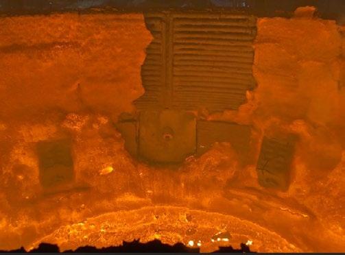
Operational learnings identified two primary technology enhancement opportunities: the current system operation relies on energy input estimation rather than real-time slag height measurement; future development may incorporate:
• electrical arc signal harmonics;
• acoustic monitoring;
• off-gas analysis;
• thermal imaging. This would enable predictive de-slagging automation. Cold slag accretion removal capability may be improved through:
• increased hydraulic pushing force by installation of a hydraulic power pack with higher hydraulic pressure;
• SwingDoorTM, including its hydraulic actuator, is designed for hydraulic pressure up to 210 bar. Actually, it is used with only approx. (120 bar).
These enhancements would improve closure reliability in high-slag DRI operations.
The INTECO PTI SwingDoorTM system has improved the operation of the EAF’s at C.M.E. facility by eliminating the slag door area as a cold spot, controlling the removal of slag. The design of the SwingDoor TM allows the slag door area to remain closed during the melting and refining stages of the heat. While the SwingDoor TM was designed to retain more of the slag in the EAF, operators at the same time gained more control over when slag leaves the furnace and the amount of slag that leaves the furnace. In addition, a significant reduction in FeO, energy, electrode and lime consumption was experienced.
Special thanks to the melt shop and maintenance management teams in C.M.E. for their support and trust in this technology, their diligence in design, attention to detail and for their input in practice development that helped make these installations successful.
[1] Leber M., Marterer P., Buchmaier C., Redl C., Valoppi A. SWINGDOORTM, HYBRID BURNER & REAL-TIME OFFGAS ANALYSIS - a full technological package to immediate reduce CO2 emissions in EAF operation, EEC 2024, Essen, GERMANY
[2] Campa T., Shikhmetoff P., PTI SwingDoorTM Design changes, Installation, and Application CMC Steel Texas and CMC Steel South Carolina, AISTECH 2024, Ohio, USA
[3] Shikhmetoff P. EAF operational results of after switching to INTECO PTIs Chemical energy and SwingDoorTM, IAS 2024, Santa Fe, Argentina
A. Lanari, M. Daita, D. Beacco
In the blooming market of minimill plants, our latest plant at Hybar, Osceola, Arkansas, started up 630,000 tpy rebar production in September 2025, setting new benchmarks for productivity, performance, safety, and environmental emissions while fully meeting the requirements of a CMT minimill. This paper presents the latest EAF technologies, including the X-Pact® AURA DC power supply, Condoor®, X-Pact® Sampler, SafEBT equipment, as well as the Spray Systems design, and their impact on green steel production.
KEYWORDS: ELECTRIC STEELMAKING TECHNOLOGIES; CONTINUOUS MICROMILL; SMS CMT®; SMS X-PACT® AURA™ DC EAF; PRODUCTIVITY; POWER FEEDING; EFFICIENCY.
SMS’s newest facility for Hybar in Osceola, Arkansas, commissioned a 630,000 tpy rebar production plant in September 2025. Located strategically on the Mississippi River with direct access to a dedicated river port, the site is ideally positioned to serve as an ultra-regional supplier, supporting cost-efficient deliveries throughout the United States. The facility also features a 104 MW solar installation across a 1,300-acre site, representing the nation’s largest behind-the-meter solar and battery storage system. As a result, Hybar has become the first—and currently the only—steel plant able to produce steel using 100% solar energy during daylight hours.
The development of a CMT® (Continuous Mill Technology) micromill of this scale [1, 3] requires the integration of innovative technologies into the project, including:
• an EDGE Electric Arc Furnace powered by the X-Pact® AURA™ DC power supply;
• a continuous caster equipped with a CONREX® large-corner, high-speed mold;
• a rolling mill featuring industry-leading solutions, including single-pass finishing through the individually driven MEERdrive® high-speed blocks. This paper presents the key technology features of an Electric Arc Furnace designed for CMT® plants.
Meltshop layout
The plant layout has been optimized to suit the selected site (figure 1). The equipment is arranged along a north-tosouth axis, with the heavier and taller structures concentrated in the steelmaking area and the lighter, lower-profile installations located within the rolling mill section. A dedicated roll shop, along with a ladle and tundish relining area, is positioned adjacent to the main bay.
A fleet of overhead cranes supports plant operations across the facility. In the Electric Arc Furnace bay, two 233 t cranes handle scrap buckets, liquid steel transfers, and are designed to accommodate full shell replacement in a single-lift exchange procedure. The ladle and tundish maintenance area is equipped with a 60 t crane. In the rolling mill, 30 t and 20 t cranes serve the operations, while finished product handling is managed by two additional 30 t cranes.
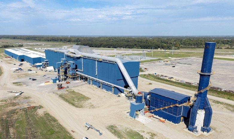
The steelmaking plant (figure 2) is located on the north side and has been configured to support single-bucket
charging, rapid-shell exchange, and a safe ladle maintenance cycle.
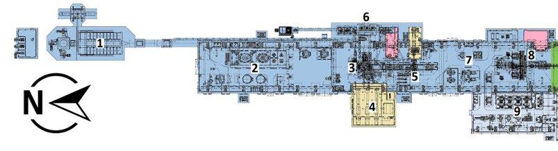
To reduce transfer distances and crane travel, SMS selected a compact layout in which the Electric Arc Furnace (EAF) and Ladle Furnace (LF) are aligned on the same axis
and share the same ladle car tracks (figure 3). A total of two electrically driven ladle cars is installed, ensuring both reliability and redundancy in the refining area.
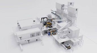
This arrangement enables the use of a shared control room, from which operators can oversee both the Electric Arc Furnace and the Ladle Furnace (figure 4). Reducing personnel requirements while increasing the level of au-
tomation is a key factor in achieving the high productivity and operational success of the CMT® meltshop. The two operating platforms are connected by walkways, allowing smooth movement between the different work areas.
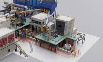
To further reduce the overall footprint, particular attention was given during the engineering phase to minimizing the area required for the Material Handling System (figure 5). The result is a compact arrangement featuring in-line silos and a single common loading point. Between the three lime, dololime, and carbon silos serving the EAF and the eight ferro-alloy silos dedicated to the tapping la-
dle and LF, space was also allocated for the installation of three additional silos for furnace carbon injection. In addition, all working platforms are interconnected, and operator access—where required—has been carefully designed to reduce travel distances and minimize time and effort.
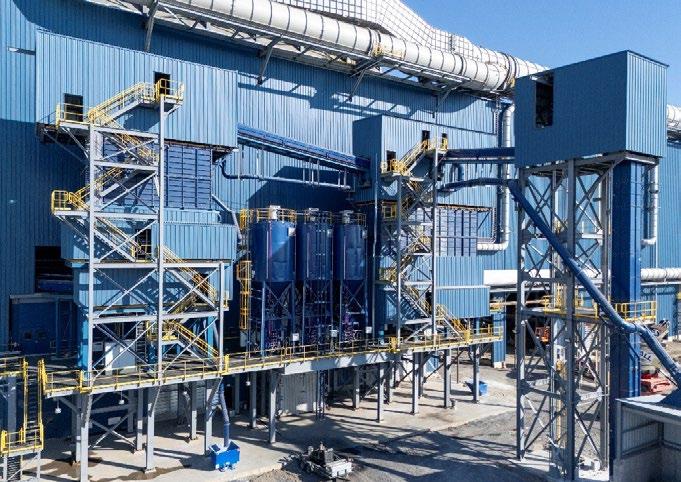
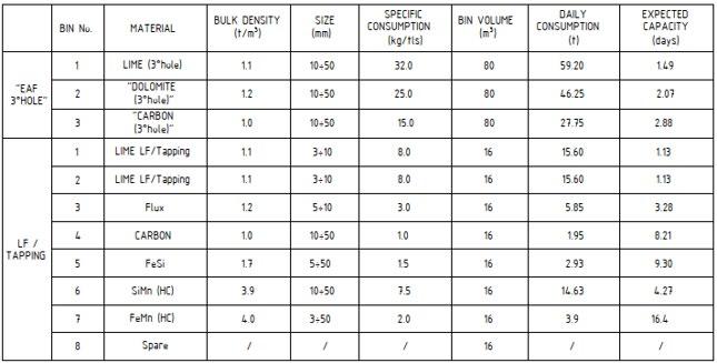
The shell maintenance area reflects the strong commitment of SMS and Hybar to safety and environmental performance. A movable hood above the lower-shell refractory de-bricking stand is directly connected to the secondary line of the approximately 1.5 million Nm³/h (approximately 900,000 scfm) Gas Cleaning Plant. The main baghouse, based on a pulse-jet design, is located immediately outside the maintenance area, reducing both distance and investment requirements while still providing an adequate safety margin for full-power EAF operation.
Between the shell maintenance area and the EAF operating platform, scrap buckets are transported by dedicated trailers. Hybar has opted for an external open scrap yard,
where the buckets are prepared before being dispatched to the meltshop bay. Scrap quality and weight recipes are managed by the automation system and exchanged in real time with the EAF process control system.
At the center of the steelmaking area is the EAF EDGE design, complemented by X-Pact® AURA™ DC technology. SMS has standardized the size range and design of Electric Arc Furnaces for CMT® applications. The main furnace sizes currently available are as follows:
• heat size 35 t (38 sht) for CMT350;
• heat size 50 t (55 sht) for CMT550;
• heat size 70 t (77 sht) for CMT700.
The EDGE DC furnace for CMT® is equipped with sidewall-mounted modular oxygen injectors, eliminating the need for lance manipulators, furnace wall openings, and “open-door” operation. In future, the Conso® technologies installed at Hybar will be succeeded by new JetLite® combined burner injectors. Developed in close collaboration with steelmakers, this burner is designed to maximize user-friendliness while simplifying operation and maintenance.
With the Condoor®, the furnace can operate primarily with the slag door closed, reducing the ingress of excess air into the shell and thereby improving energy efficiency. The Condoor® is actuated by double-acting hydraulic cylinders and operated automatically. In combination with the X-Pact® Sampler robot, it also enables unmanned operation at the slag door (figure 6).
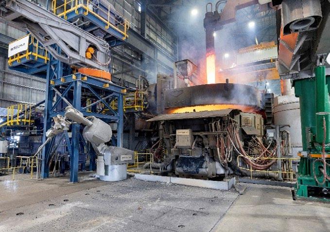
Single-point roof lifting is a key element of the mechanical design. A single heavy-duty cylin-der actuates lifting and lowering of the roof, enabling it to be disconnected without operator in-tervention, with the only exception being the decoupling of the water hoses. The following ben-efits are associated with this design:
• more space above the roof;
• faster delta refractories and delta ring replacement;
• faster roof and shell exchange procedure;
• lifting speed from 50 to 100 mm/s.
SMS partners with Systems Spray-Cooled™, delivering a state-of-the-art furnace body com-bined with the consolidated Spray-Cooled™ upper shell and roof design (figure 7).
The Spray-Cooled™ equipment includes the furnace sidewall, roof, and elbow. As part of the project, Systems supplied its new B.A.S.S. Multi-Element Bag Strainer™ system, which pro-vides enhanced filtration and contributes to extended equipment life. The decision by SMS and Hybar to install Spray-Cooled™ equipment was driven by its advantages in safety, ease of maintenance, and environmental performance, making it one of the most sustainable furnace equipment solutions available.
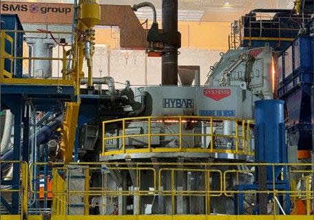
The DC configuration (figure 8) provides strong natural vertical stirring, which enhances bath mixing and improves temperature homogenization. This leads to shorter power on time and lower electrical energy consumption.
In addition, reduced carbon injection and natural gas usage help decrease emissions and minimize the overall CO2 footprint.
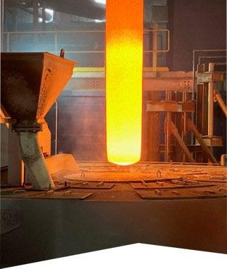
The X-Pact® AURA™ DC power-feeding system (figure 9) [2] delivers a clean electrical load with low losses in the high-current circuit, a high-power factor, rapid electrode control, and low total harmonic distortion while also being designed for integration with renewable energy sources. The furnace is rated at an average of 46 MW and
features conductive arms connect-ed to the 24-inch electrode, which is controlled by the SMS SynReg® regulation system. In combination with the electrode regulation system, power electronics enable more flexible arc control than conventional AC and DC power systems.
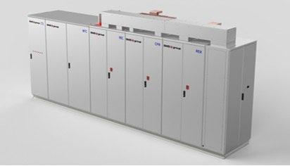
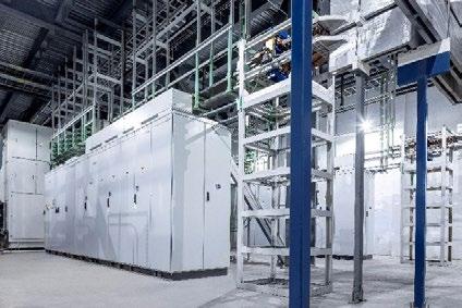
- X-Pact® AURA™ installation in the EAF power-feeding room.
Hybar meltshop main design data
The main characteristics of the CMT® meltshop currently in operation in Osceola are summa-rized below:
Tab.1 - Main design technical data.
injector (qty. / flow)
The Hybar team and SMS group finalized the technology supply in August 2023. Most of the equipment was manufactured in Europe, with site deliveries taking place in stages throughout the second half of 2024. Erection activities continued during the first half of 2025 and were subsequently followed by commissioning with the following key 2025 milestones:
• September 14: First arc on the new X-Pact® AURA™ DC furnace.
• September 16: First continuous cast achieved at an initial commissioning speed of 4.6 m/min and rolled in endless mode.
• October 9: Stable endless rolling practice established.
• October: First production shipments to customers.
At the end of 2025, with commissioning still ongoing, the plant achieved the following perfor-mances:
• 28 heats in 24 hours (75% of planned capacity), including 22 heats in full continuous rolling mode.
• Record tap-to-tap time of 33 minutes (nominal time improved by 10%).
• Liquid steel energy consumption of 380 kWh/t (nominal power consumption improved by 15%).
• Power factor > 0.96.
The plant is in the final commissioning phase with the defined performance improvements al-ready demonstrated.
Next steps are continued commissioning, optimization to reach full rated capacity, and handover to sustained commercial operation.
Extended data was collected and analyzed throughout December 2025 and January 2026, primarily focusing on the performance of the EAF. It is worth mentioning that not all the preconditions were in place for full appraisal; nevertheless, the results of the site offered some evidence. The X-Pact® AURA™ system has delivered an exceptionally high level of reliability from day one. Full power was achieved after only three heats, reflecting the extensive development work behind the technology. Its ramp-up was faster than that of any comparable advanced solution previously introduced by SMS group.
This performance is demonstrated by the stable and consistent power on time shown in figure 10, while the best shifts recorded power on times of 30 minutes or less, as illustrated in figure 11. At the same time, the EAF is not yet operating at full power, as the average power shown in figure 10 remains below 35 MW compared with the nominal 46 MW. This highlights the plant’s significant remaining potential. SMS’s target is to achieve a consistent power on time of below 30 minutes, which would position the Hybar EAF among the world’s top performing furnaces.
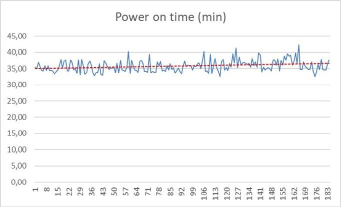
- December-January: Power on time.
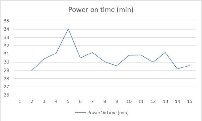
Electrical energy consumption
The analysis of electrical energy consumption indicates a stable operating trend, with average values in the range of 370-400 kWh/tls and best heats achieving figures well below 360 kWh/tls (figure 12). These results are comparable to those reported for most U.S. sidewall horizontal scrap preheating installations. This represents a signifi-
cant achievement, confirming both the soundness of the design and the effectiveness of the selected technologies. The data should, however, be evaluated in relation to the quality of the scrap charged into the furnace: the proportion of return scrap has increased in recent periods, and the influence of heavier, denser material should therefore be considered when interpreting these figures.
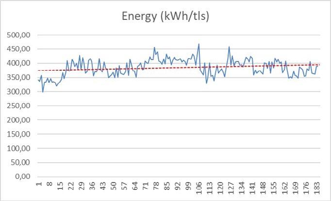
- December/January: Electrical consumption vs. scrap type.
Natural gas
Natural gas consumption has been consistently maintained below 5 Nm³/tls (see figure 13). During the latter part of January, a further significant reduction was achieved, bringing consumption well below 4 Nm³/tls (see figure 14). This represents a notable performance,
particularly in view of the single-bucket operating practice and the furnace size. With an appropriate balance between electrical energy input and burner input, the furnace can melt the single bucket efficiently and initiate oxygen lancing at a very early stage.
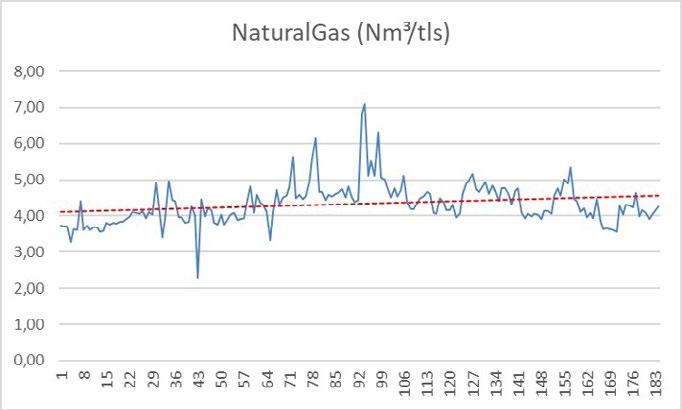
Fig.13 - December/January: Natural gas consumption vs. scrap type.
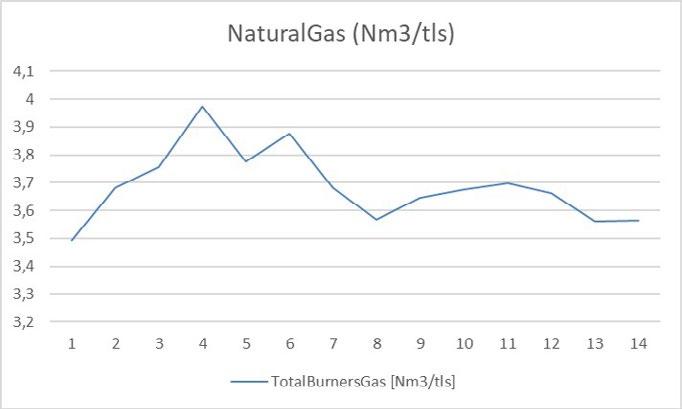
Fig.14 - One shift: natural gas consumption.
This further demonstrates the strong commitment of Hybar and SMS group to achieving the lowest CO2 footprint ever recorded in rebar production.
Consolidated performance
To provide a clearer view of the consolidated performance, figure 15 illustrates the tap-to-tap time as a function of tapping weight and electrical energy consumption; it is also worth noting that the average tapping temperature is approximately 1,650 °C (3,002 °F).
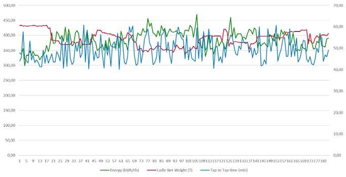
- December/January: EAF consistency.
SMS group and Hybar are now working closely together to further enhance performance and minimize variability in the key operating parameters. It is well understood that consistent pro-duction conditions are essential to ensuring stable, high-throughput rebar production.
The CMT® meltshop requires a customized design approach, and the Hybar furnace has confirmed the validity of the selected solutions. Although further improvements are still being pursued, the Electric Arc Furnace has already demonstrated outstanding performance and offers
a strong basis for continued development. Standardization of the CMT® meltshop concept across different production capacities will help reduce both engineering lead time and, more importantly, commissioning effort. The single-bucket EDGE configuration, combined with the X-Pact® AURA™ DC EAF technology, has proven to be a high-performing solution, achieving results comparable to those of the best U.S. horizontal scrap preheating systems. SMS group and Hybar will continue their close cooperation to further increase productivity and support the achievement of Hybar final targets.
[1] Aistech 2026 - Raising the (re)bar - The new 630,000 tpy continuous micromill at Hybar in Osceola, AR breaks new ground for energy efficient, environmentally friendly, AI supported and safe rebar production; SMS group; Hybar LLC;
[2] Aistech 2026 - AURA digital arc furnace power supply for green steel production; SMS group;
[3] Aistech 2024 - Continuous Mill Technology for Efficient Production of Long Products; SMS group;
[4] Aistech 2026 - Electric Arc Furnace for direct bar casting and rolling; SMS group;
Principi di sicurezza, limiti metallurgici e misure cautelative
a cura di Guido Capoferri
La presente nota tecnica non è una procedura operativa, non sostituisce le procedure operative aziendali, non è un manuale di saldatura, ma un documento di inquadramento, sicurezza e limiti. Nasce da una riflessione professionale scaturita dall’analisi di un recente caso di rottura di rotaia saldata in esercizio e si fonda su una ricerca personale di carattere generale, condotta su riferimenti normativi, prassi operative e documentazione tecnica di settore, ed è il risultato di un approfondimento tecnico personale, redatto a scopo informativo generale e privo di finalità peritali o valutative su casi specifici.
PREMESSA
La sicurezza dell’infrastruttura ferroviaria è strettamente connessa all’integrità metallurgica delle rotaie e alla corretta esecuzione degli interventi di manutenzione in campo.
Le rotaie moderne, realizzate in acciai a elevato tenore di carbonio (≈0,60% C), presentano caratteristiche meccaniche elevate ma, al contempo, significative criticità in relazione ai processi di saldatura ad arco tradizionali. Gli interventi di ripristino eseguiti in condizioni di urgenza operativa richiedono pertanto una valutazione attenta dei limiti metallurgici del materiale, dei gradienti termici indotti e delle possibili trasformazioni strutturali in zona termicamente alterata (ZTA).
La presente nota tecnica si propone di richiamare, in forma sintetica e generale, i principi di sicurezza, i vincoli metallurgici e le misure cautelative che devono essere considerati negli interventi di saldatura delle rotaie in campo, con l’obiettivo di favorire un approccio tecnicamente consapevole e coerente con le buone pratiche del settore.

“La sicurezza non è mai definitiva: è un processo continuo di controllo, valutazione e miglioramento.”
D EFINIZIONE DI BINARIO E ROTAIA
Il binario ferroviario è l’infrastruttura alla base di una linea ferroviaria o tranviaria; è una struttura composta da due guide metalliche parallele, le rotaie, su cui transitano treni o tram.
Le rotaie sono una componente essenziale dei nostri sistemi di trasporto e svolgono un ruolo cruciale sia nella circolazione delle merci sia delle persone.
ROTAIE
Le rotaie sono profilati metallici in acciaio montati su una struttura in legno o cemento armato, detta traversa, per mezzo di sistemi di fissaggio (questo sistema nel suo insieme viene detto armamento ferroviario) e rappresentano l’elemento fisso della coppia cinematica necessaria al moto dei rotabili; ha la funzione di supportare il peso e di guidare le ruote dei veicoli ferroviari. In aggiunta alla forma, la rotaia è caratterizzata dal peso per metro di lunghezza.
Essendo il mezzo di contatto diretto tra il treno e il binario, la qualità delle rotaie influisce direttamente sulla sicurezza, la stabilità e l’economicità del trasporto ferroviario.
Questo prodotto è realizzato in acciaio legato ad alta resistenza, combinato con un trattamento termico avanzato e una tecnologia di lavorazione di precisione, per soddisfare i requisiti di utilizzo a lungo termine in presenza di carichi pesanti, alta velocità e ambienti geologici complessi, e ampiamente utilizzato nelle ferrovie principali, nel trasporto ferroviario urbano, nelle linee dedicate al settore minerario e nelle ferrovie industriali.
CARATTERISTICHE CHIMICHE, MECCANICHE E DIMENSIONALI DELLE ROTAIE
La sezione della rotaia è convenzionalmente suddivisa in tre parti principali:
- fungo, destinato al contatto con la ruota e alla guida dei bordini;
- gambo, che collega il fungo alla suola e può presentare fori in corrispondenza delle giunzioni;
- suola, appoggiata sulla traversa e vincolata mediante i sistemi di attacco sulla traversa e vincolata ai sistemi di attacco. Oltre alla geometria, la rotaia è caratterizzata dal peso per unità di lunghezza, parametro di continuità geometriche funzionale dell’armamento ferroviario.
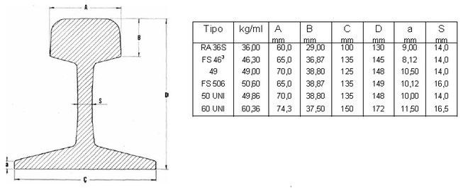
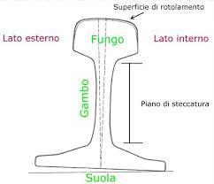
Tab.1 - Schema sintetico per scelta del grado.
Condizione di servizio
Rete leggera / traffico passeggeri
Binari convenzionali con traffico standard
Alte prestazioni, traffico intenso / alta velocità
Situazioni con usura severa
Grado raccomandato
R200 / R220
R260 / R260Mn
R320Cr / R350HT / R350LHT
Gradi con C e Cr elevati
Tab.2 - Caratteristiche meccaniche delle rotaie.
Grado acciaio Tensile Strenght (Rm) Allungamento min (%) Durezza HBW (tipica)
COMPOSIZIONE CHIMICA DEGLI ACCIAI DA ROTAIA
Tali valori collocano gli acciai per rotaie in un campo di elevata sensibilità alle cricche a freddo, tempra martensi-
tica e fragilità da idrogeno, rendendo inapplicabili alcuni criteri ordinari di saldabilità.
Tab.3 - Composizione chimica degli acciai da rotaia.
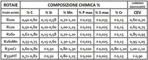
Gli acciai ad alto tenore di carbonio sono saldabili esclusivamente mediante processi dedicati e con controllo termico rigoroso.
Tab.4 - Classificazione corretta della saldabilità
Grado rotaia
R200 – R220
R260 – R260Mn
R320Cr
R350HT / LHT
Alcuni limiti di applicabilità della saldatura in campo a) non è una soluzione permanente di “progetto”; b) non idonea a: - rotaie fortemente incrudite - difetti estesi nel fungo - gradi HT/LHT salvo procedure speciale GI (Gestore delle Infrastrutture)
Per interventi urgenti, con procedimenti qualificati WPS e WPQR (per esempio saldatura alluminotermica o saldatura elettrica dedicata), la saldatura in campo consente di ridurre i tempi di indisponibilità della linea rispetto alla sostituzione integrale del tratto di rotaia, risultando idonea per difetti localizzati, purché le condizioni di esercizio lo consentano.
WPS E WPQR: IN COSA CONSISTONO
Acronimi, rispettivamente, di Welding Procedure Specification e Welding Procedure Qualification Report, sono
Saldabilità
Poco saldabile
Difficilmente saldabile
Quasi non saldabile
NON saldabile con processi standard
i due documenti alla base di ogni processo di saldatura. Essi descrivono procedure tecniche conformi a standard e regolamenti a norma di legge molto specifici.
La sigla WPS fa riferimento a tutta la serie di procedure e operazioni di fabbricazione relative alla saldatura del giunto di qualifica.
Con la sigla WPQR si fa invece riferimento al report di qualificazione della procedura di saldatura, in cui sono inseriti tutti i risultati delle prove di saldatura e che qualifica il saldatore per l’esecuzione della procedura. La saldatura in campo è ammessa, ma non è neutra, né banale, e va governata.
Gli interventi manutentivi sono subordinati:
- All’applicazione di procedure di saldature qualificate;
- Al rispetto delle prescrizioni normative vigenti;
- All’osservanza delle istruzioni e delle autorizzazioni
del Gestore dell’Infrastruttura direttamente correlato alle prestazioni meccaniche e all’ambito di impiego.
La saldatura delle rotaie eseguita in campo rappresenta una soluzione tecnica ammessa per interventi di manutenzione correttiva rapida, finalizzati al ripristino della continuità geometrica e strutturale dell’armamento ferroviario, purché effettuata nel rispetto delle procedure qualificate e delle prescrizioni normative applicabili, e dalle istruzioni del gestore dell’infrastruttura.
Gli acciai per rotaie disciplinati dalla UNI EN 13674-1 sono caratterizzati da alto tenore di carbonio ed elevato equivalente di carbonio (CEV).
In ambito metallurgico e normativo, tali materiali non sono saldabili secondo il concetto classico di saldabilità degli acciai strutturali. La formulazione tecnicamente corretta è: “Acciai ad alto tenore di carbonio, saldabili esclusivamente mediante processi dedicati e con controllo termico rigoroso.”
A titolo indicativo, gli acciai più diffusi (R260, R260Mn, R320Cr) presentano tenori di carbonio tipicamente compresi tra 0,65 e 0,80 % e valori di CEV generalmente superiori a 0,85, con elevata sensibilità a cricche a freddo e strutture temprate. Tali caratteristiche rendono necessario un approccio prudenziale alla gestione dell’intervento. La UNI EN 13674-1:2017 (in vigore) specifica le rotaie ferroviarie tipo “Vignole” di massa lineare ≥ 60 kg/m, incluse proprietà di materiale, tolleranze geometriche e prove di accettazione. Per interventi urgenti, la saldatura in campo (es. saldatura alluminotermica o saldatura elettrica dedicata) consente di ridurre i tempi di indisponibilità della linea, rispetto alla sostituzione integrale del tratto di rotaia.
ALCUNI TIPI DI SALDATURA IN CAMPO
- Saldatura allumino termica o H atomica EN 14730, tecnica ampiamente utilizzata nel settore ferroviario per la saldatura di rotaie in opera o in stabilimento, grazie alla capacità di creare giunzioni resistenti in tempi brevi senza ausilio armamento ferroviario.
- Saldatura a scintillio (Norma EN 14587-1-2 - Flash Butt Welding (FBW)) utilizza armamento ferroviario nell’ambito industriale o su linea attrezzata.
- Saldatura alluminotermica o H atomica (EN 14730).
La base per il processo di saldatura alluminotermica Il processo dell’alluminotermia (detto anche processo Goldschmidt) sfrutta il calore prodotto durante la reazione di ossidazione dell’alluminio metallico in presenza di ossido ferrico (Fe2O3): 2 Al + Fe ₂ O ₃ → Al ₂ O ₃ + Fe + calore. Ebbe origine nel 1895, sviluppato dal chimico tedesco Hans Goldschmidt.
La saldatura Thermit© è un processo di saldatura a fusione esotermica che sfrutta una reazione tra un ossido metallico (tipicamente ossido di ferro) e polvere di alluminio per generare metallo fuso da unire. Non richiede né utilizza energia esterna sotto forma di arco elettrico o gas: basta una scintilla per accendere la miscela, o termite. Ciò che si genera è una pozza di metallo liquido altamente surriscaldato che riempie uno stampo, fondendo le parti una volta raffreddato.
La saldatura “alluminotermica” viene utilizzata principalmente per la saldatura autogena dei binari ferroviari sfruttando la reazione esotermica della termite. La reazione avviene miscelando tra loro una parte di alluminio metallico (Al) con tre parti di ossido ferrico (Fe2O3). La miscela così ottenuta (termite) viene posta all’interno di un crogiolo e innescata mediante rapido riscaldamento: uno dei metodi utilizzabili è la combustione di un nastro di magnesio (M). La reazione porta alla formazione di ossido di alluminio (Al2O3) e di ferro metallico (Fe) fuso, data alta temperatura (3000 °C). La saldatura si effettua ponendo ai lati delle rotaie da saldare della terra refrattaria utilizzata per creare uno stampo che impedisca la fuoriuscita del metallo fuso. Una volta preparato il crogiolo contenente i reagenti viene posto al di sopra dei binari e si procede all’accensione della termite. L’enorme sviluppo di calore sarà tale da portare a fusione le parti da saldare unendo così le rotaie in un tutt’uno.
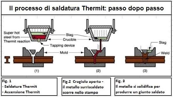
Fasi del processo di saldatura alluminotermica Thermit©.
Gli acciai per rotaie non sono assimilabili agli acciai strutturali da carpenteria ordinaria. L’elevato contenuto di carbonio e il valore di CEV comportano: - maggiore sensibilità alla formazione di martensite in ZTA (Zona Termica Alterata); - rischio di cricche a freddo; - necessità di rigoroso controllo dei parametri termici.Pertanto, la saldatura delle rotaie deve essere eseguita esclusivamente mediante procedimenti qualificati e secondo specifiche tecniche validate. In specifiche condizioni operative, al fine di incrementare il livello di sicurezza complessiva dell’intervento, può essere adottata una soluzione integrata, costituita dalla saldatura della rotaia associata a un bloccaggio meccanico ausiliario mediante due piatti forati fissati sull’anima della rotaia con bulloneria idonea.
Il metodo di giunzione prevede l’uso di piastre metalliche con quattro fori dette piatti o stecche di giunzione, poste a coppie lateralmente sul gambo delle due rotaie da unire e imbullonare mediante chiavarde di giunzione.
Tale giunzione è da intendersi esclusivamente come misura cautelativa, temporanea e reversibile, finalizzata a introdurre una ridondanza strutturale dell’intervento e a contenere le conseguenze di eventuali difetti iniziali della giunzione saldata e a migliorare l’affidabilità dell’intervento durante l’esercizio, soprattutto in fase transitoria o fino alla manutenzione definitiva. Esso non sostituisce né modifica la funzione strutturale della saldatura, né configura una soluzione permanente.
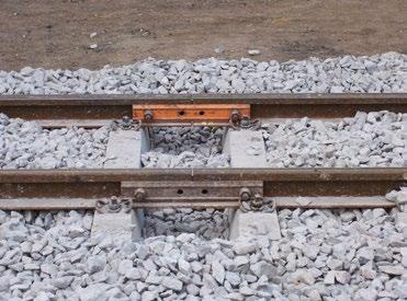
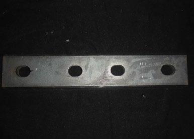
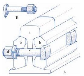
La chiavarda da rotaia è un organo di collegamento simile al bullone, da cui differisce per il sistema di serraggio che può essere a bietta anziché a dado; è composta da una testa (spesso sagomata per evitare che ruoti), una parte liscia che attraversa la sezione della rotaia, e infine la parte filettata su cui andrà a fissarsi il dado. Nelle ferrovie le chiavarde sono usate per stringere le ganasce di giunzione delle rotaie: la testa a becco (b) impedisce la rotazione della chiavarda, quando si stringe il dado (d) (vedere figura sopra dx).
L’intervento deve essere eseguito con Procedimenti
Qualificati (WPS), Specifiche di Procedura di Saldatura e Qualifica dei Procedimenti di Saldatura (WPQR), Registro delle qualifiche delle procedure di saldatura, da personale abilitato, corretta preparazione dei lembi, l’allineamento delle estremità delle rotaie, controllo del ciclo termico, finitura del profilo e controlli post-intervento adeguati alla classe di linea.
Alcune indicazioni a carattere generale per il processo di saldatura alluminotermica.
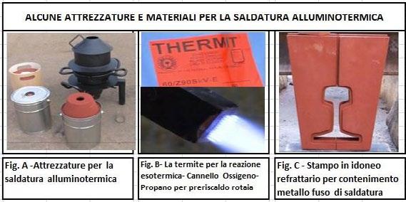
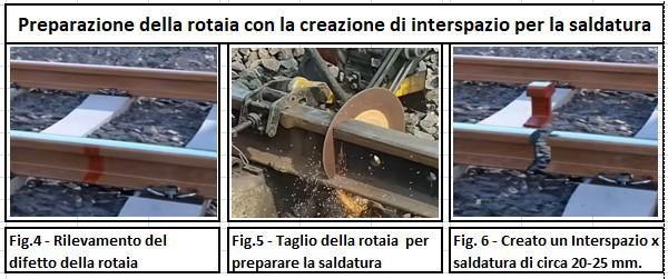
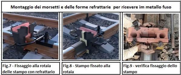
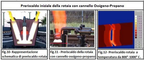
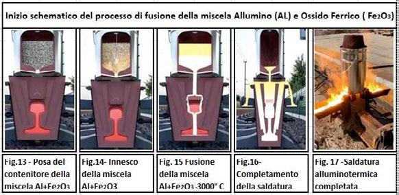
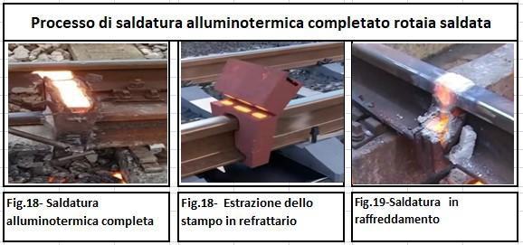
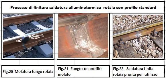
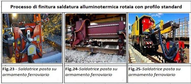
SALDATURA A SCINTILLIO (NORMA EN 14587-1-2FLASH BUTT WELDING (FBW))
In sintesi, la saldatura a scintillio (o flash welding) è un processo che unisce due componenti metallici tramite il riscaldamento delle superfici da saldare, generato da scariche elettriche intermittenti ad alta intensità. Il riscaldamento localizzato produce la fusione delle estremità che, una volta raggiunta la temperatura ideale, vengono unite con una pressione controllata.
Questo tipo di saldatura è particolarmente efficace per sezioni medio-grandi, dove è necessario garantire un’unione forte e continua, senza l’aggiunta di materiale di apporto.
Una forza di 1500 kN e una lunghezza di tiro fino a 200 mm permettono l’esecuzione di saldature di neutralizzazione delle tensioni interne della rotaia.
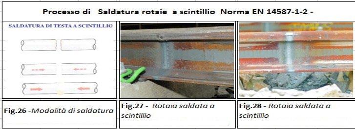
La saldatura a scintillio (EN 14587 Flash Butt Welding (FBW)) rappresenta la soluzione preferenziale nei seguenti scenari:
• realizzazione di rotaie lunghe saldate (LRS);
• produzione in stabilimento o in impianti attrezzati;
• ad alta velocità o elevato carico assiale;
• costruzioni o rinnovi integrali di linea;
• situazioni in cui è richiesta elevata uniformità metallurgica e ripetibilità del processo.
Tale procedimento garantisce superiori caratteristiche meccaniche, migliore omogeneità strutturale e minore incidenza di difettosità, a fronte tuttavia di maggiori vincoli logistici, necessità di impianti dedicati e costi iniziali più elevati.
In termini generali:
→ Manutenzione in linea e interventi localizzati → Saldatura alluminotermica
→ Nuove costruzioni, linee AV/AC e produzione industriale → Saldatura a scintillio
La scelta definitiva dovrà comunque essere coerente con:
• specifiche del Gestore dell’Infrastruttura; le normative tecniche vigenti;
• le condizioni di esercizio della linea; valutazioni di sicurezza e qualità richieste dal progetto.
Tab. 5
Parametro
Ambito di impiego
Logistica
Qualità metallurgica
Ripetibilità
Prestazioni meccaniche
Tempi operativi
Costi iniziali
CONCLUSIONI
Saldatura alluminotermica
Interventi di linea e manutenzione
Elevata flessibilità operativa
Buona, dipendente dall’esecuzione
Media
Adeguate per esercizio ordinario
Maggiori tempi di raffreddamento
Contenuti
Da tecniche metallurgiche e normative esposte, la saldatura delle rotaie eseguita in campo deve essere considerata un intervento a elevata criticità, ammissibile esclusivamente nell’ambito di operazioni di manutenzione correttiva in tempi ridotti e nel rigoroso rispetto delle procedure qualificate, delle prescrizioni normative vigenti e delle disposizioni del Gestore dell’Infrastruttura.
Gli acciai per rotaie, disciplinati dalla UNI EN 13674-1, caratterizzati da elevato tenore di carbonio ed elevato equivalente di carbonio, presentano una saldabilità intrinsecamente limitata e una marcata sensibilità ai fenomeni metallurgici avversi, quali la formazione di strutture temprate e l’innesco di cricche a freddo.
Tali caratteristiche impongono un approccio fortemente prudenziale nella pianificazione, esecuzione e gestione dell’intervento. Ne consegue che la saldatura in campo non può essere assimilata a un processo industriale standardizzato, né considerata equivalente, in termini di af-
RIFERIMENTI
[1] https://www.ferrovia-lucca-aulla.com/i-lavori.html
Saldatura a scintillio
Produzione industriale e rinnovi
Necessità impianti dedicati
Elevata e uniforme
Molto elevata
Superiori, idonee per AV/AC
Processo più rapido e controllato
Elevati (impianti e attrezzature)
fidabilità strutturale e ripetibilità, ai processi di saldatura eseguiti in ambiente controllato. Eventuali soluzioni integrative o cautelative, quali giunzioni meccaniche, non costituiscono alternativa strutturale permanente alla saldatura, ma esclusivamente misure di supporto temporanee.
La sicurezza dell’esercizio ferroviario non può pertanto essere affidata al solo esito immediato dell’intervento, ma deve essere garantita mediante una valutazione complessiva che tenga conto dei limiti metallurgici del materiale, delle condizioni operative, del controllo del processo e del monitoraggio nel tempo del giunto realizzato. In tale contesto, la fiducia tecnica nella sicurezza dell’armamento ferroviario deve essere intesa come un processo continuo, fondato sulla competenza, sul rispetto delle regole e sulla consapevolezza dei limiti intrinseci dei materiali e delle tecnologie impiegate.
“La fiducia tecnica sulla sicurezza ha un inizio, ma mai una fine.”
[2] https://it.wikipedia.org/wiki/File:Verschraubter_schienenstoss.jpeg
[3] https://longafer.it/it/
[4] https://www.treccani.it/enciclopedia/chiavarda/
[5] https://it.wikipedia.org/wiki/Termite_%28miscela%29
[6] https://www.thermit.it/
Il professor Carlo Mapelli, Docente del Politecnico di Milano e figura di riferimento a livello nazionale e internazionale nel campo della metallurgia e dei materiali, torna alla guida di AIM dopo aver già ricoperto la Presidenza dell’Associazione nel biennio 2014-2018. Il nuovo Presidente raccoglie il testimone da Silvano Panza, che conclude il proprio mandato dopo quattro anni caratterizzati da una significativa crescita delle attività associative e dal rafforzamento del ruolo di AIM quale punto di riferimento per il dialogo tra ricerca, industria e formazione.
La nomina di Carlo Mapelli arriva in una fase particolarmente significativa per il mondo dei materiali, chiamato a confrontarsi con sfide sempre più complesse legate alla sostenibilità, alla transizione energetica, alla digitalizzazione dei processi e alla competitività del sistema industriale europeo.
Sotto la guida del nuovo Presidente, l’Associazione proseguirà il proprio percorso di crescita, rafforzando il dialogo tra università, centri di ricerca, aziende e professionisti e consolidando il proprio ruolo di piattaforma di confronto sui temi che stanno ridefinendo il futuro dell’industria dei materiali.
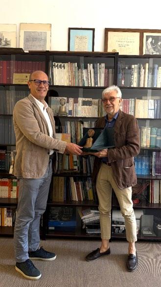
Il28maggio2026,inoccasionedelconsigliodirettivoAIM,ilpresidenteuscenteSilvanoPanzahaconferitolamedaglia d'oro "Walter Nicodemi" a Mario Cusolito, direttore de La Metallurgia Italiana, come riconoscimento per il suo impegno nel rendere la nostra rivista una fonte autorevole nel panorama delle scienze dei materiali e della metallurgia, e comemembrodinumerosicomitatiscientificietecnicidell’AssociazioneItalianadiMetallurgia.
“Nell’anno dell’80esimo anniversario di AIM, il consiglio ha scelto di celebrare chi ha reso la nostra Associazione ciò che è oggi; ricordando il compianto professor Walter Nicodemi, abbiamo deciso di conferire il primo premio e medaglia dedicati alla sua memoria al direttore della rivista La Metallurgia Italiana Mario Cusolito, che ha dedicato altrettanto impegno ed entusiasmo nel rendere grande la nostra Associazione”, queste le parole del presidente uscente Panza nelpremiareildirettoreconlamedagliaallapresenzadellafigliadelprofessorNicodemiElenaNicodemiedellanipote AntonellaDonzelli.



11-12-13 MAY 2027 | HALLS 8-12-16 FIERA MILANO RHO, MILAN ITALY

POWERED BY
BY Scan here to secure your place at the 2027 edition




Corso Fonderia per non fonditori Capire la fonderia per scegliere meglio (Webinar Zoom) - 25-26 giugno, 2-3-7-8-9 luglio 2026
>> SCOPRI DI PIÙ
Summer School Digitalization & AI in Metallurgy Udine – 28-29-30 giugno – 1 luglio 2026
>> MORE INFO
Summer school “Environmental Assisted Cracking” Milazzo (ME) - 5-9 July 2026
>> MORE INFO
Giornata di Studio Superleghe di nichel Reggio Emilia - 7 luglio 2026
>> SCOPRI DI PIÙ
WCCM 2026
The 4th World Congress on Condition Monitoring Milano, Italy - 25-27 August 2026
>> MORE INFO


41° Convegno Nazionale AIM
Evento celebrativo AIM
Brescia - 9-11 settembre 2026
>> SCOPRI DI PIÙ
Scuola Metallurgia delle Polveri - V edizione Imola (BO) c/o SACMI - 16 - 17 settembre 2026
>> SCOPRI DI PIÙ
Giornata di Studio Evoluzione e aggiornamenti normativi nei trattamenti termici dei metalli
Webinar FaReTra - 23 settembre 2026
>> SCOPRI DI PIÙ
5th International Conference on INGOT CASTING, ROLLING & FORGING
Bardolino, Verona - 13-15 October 2026
>> MORE INFO
Tinplated Steels and Metals Packaging & Recycling - IFTSR 2026
IFTSR - International Forum Bergamo - 3-4 December 2026
>> SCOPRI DI PIÙ


ECHT 2027 & 32nd IFHTSE World Congress
The Industry meeting point for the international heat treatment and materials science network Milano (Italia) - 14-16 April 2027
>> SCOPRI DI PIÙ
GNC2027 - Giornate Nazionali sulla Corrosione e Protezione (Università di Messina - Messina, 14-16 giugno 2027
>> SCOPRI DI PIÙ
Normativa / Standards
Norme pubblicate e progetti in inchiesta (aggiornamento al 31 maggio 2026)
Norme UNSIDER pubblicate da CEN e ISO nel mese di maggio 2026
EN ISO 14577-3:2026
Metallic materials — Instrumented indentation test for hardness and materials parameters — Part 3: Calibration of reference blocks
ISO 14577-3:2026
Metallic materials — Instrumented indentation test for hardness and materials parameters — Part 3: Calibration of reference blocks
ISO 4967:2026
Steel — Determination of the non-metallic inclusion content — Micrographic method
ISO 1035:2026
Hot-rolled steel bars — Dimensions, shape, masses and tolerances
Progetti UNSIDER messi allo studio dal CEN (Stage 10.99) – giugno 2026
prEN 10352
Stainless steel plumbing fittings “Fittings with press ends for metallic tubes”
prEN 10216-1 rev
Seamless steel tubes for pressure purposes — Technical delivery conditions — Part 1: Non-alloy steel tubes with specified room temperature properties
prEN 10358
Unalloyed steel plumbing fittings — Fittings with press ends for unalloyed steel tubes
prEN 10216-3 rev
Seamless steel tubes for pressure purposes — Technical delivery conditions — Part 3: Alloy fine grain steel tubes
prEN 10216-4 rev
Seamless steel tubes for pressure purposes — Technical delivery conditions — Part 4: Non-alloy and alloy steel tubes with specified low temperature properties
Progetti UNSIDER in inchiesta prEN e ISO/DIS – giugno 2026
prEN – progetti di norma europei
prEN ISO 13503-5
Oil and gas industries including lower carbon energy — Completion fluids and materials — Part 5: Measuring conductivity of proppants (ISO/DIS 13503-5:2026)
EN ISO 16961:2024/prA1
Oil and gas industries including lower carbon energy — Internal coating and lining of steel storage tanks — Amendment 1 (ISO 16961:2024/DAM 1:2026)
prEN ISO 7039
Metallic materials — Tensile testing — Method for evaluating the susceptibility of materials to the effects of high-pressure gas within hollow test pieces (ISO/DIS 7039:2026)
ISO/DIS – progetti di norma internazionali
ISO/DIS 21826-2
Iron ores — Determination of total iron content using the EDTA photometric titration method — Part 2: Fusion decomposition method
ISO 16961:2024/DAmd 1
Oil and gas industries including lower carbon energy — Internal coating and lining of steel storage tanks — Amendment 1
ISO/DIS 13503-5
Oil and gas industries including lower carbon energy — Completion fluids and materials — Part 5: Measuring conductivity of proppants
ISO/DIS 7039
Metallic materials — Tensile testing — Method for evaluating the susceptibility of materials to the effects of high-pressure gas within hollow test pieces
Progetti UNSIDER al voto FprEN e ISO/ FDIS – giugno 2026
FprEN – progetti di norma europei
FprEN ISO 24817
Oil and gas industries including lower carbon energy — Composite repairs for piping — Qualification and design, installation, testing and integrity management (ISO/FDIS 24817:2026)
ISO/FDIS – progetti di norma internazionali
ISO/FDIS 24817
Oil and gas industries including lower carbon energy — Composite repairs for piping — Qualification and design, installation, testing and integrity management
ISO/FDIS 23414
Oil and gas industries including lower carbon energy — Workover rigs for offshore fixed platforms
ISO/FDIS 19905-4
Site-specific assessment of mobile offshore units — Part 4: Jack-up installation and removal at a site
ISO/FDIS 16630
Metallic materials — Sheet and strip — Hole expanding test
ISO/FDIS 9441
Steel — Determination of niobium content — 4-(2-Pyridylazo)-resorcinol (PAR) spectrophotometric method