Italiana La Metallurgia
International Journal of the Italian Association for Metallurgy
n.04 Aprile 2026
Organo ufficiale dell’Associazione Italiana di Metallurgia.
Rivista fondata nel 1909
International Journal of the Italian Association for Metallurgy
n.04 Aprile 2026
Organo ufficiale dell’Associazione Italiana di Metallurgia.
Rivista fondata nel 1909
International Journal of the Italian Association for Metallurgy
Organo ufficiale dell’Associazione Italiana di Metallurgia. HouseorganofAIMItalianAssociationforMetallurgy. Rivista fondata nel 1909
Direttore responsabile/Chiefeditor: Mario Cusolito
Direttore vicario/Deputydirector: Gianangelo Camona
Comitato scientifico/Editorialpanel: Marco Actis Grande, Silvia Barella, Paola Bassani, Christian Bernhard, Massimiliano Bestetti, Wolfgang Bleck, Franco Bonollo, Irene Calliari, Mariano Enrique Castrodeza, Emanuela Cerri, Vlatislav Deev, Andrea Di Schino, Donato Firrao, Bernd Kleimt, Carlo Mapelli, Denis Jean Mithieux, Roberto Montanari, Marco Ormellese, Mariapia Pedeferri, Massimo Pellizzari, Barbara Previtali, Evgeny S. Prusov, Dario Ripamonti, Dieter Senk
Segreteria di redazione/Editorialsecretary: Flynn Russo
Comitato di redazione/Editorialcommittee: Federica Bassani, Gianangelo Camona, Mario Cusolito, Carlo Mapelli, Federico Mazzolari, Flynn Russo, Silvano Panza
Direzione e redazione/Editorialandexecutiveoffice: AIM - Via F. Turati 8 - 20121 Milano tel. 02 76 02 11 32 - fax 02 76 02 05 51 met@aimnet.it - www.aimnet.it
Reg. Trib. Milano n. 499 del 18/9/1948. Sped. in abb. Post. - D.L.353/2003 (conv. L. 27/02/2004 n. 46) art. 1, comma 1, DCB UD
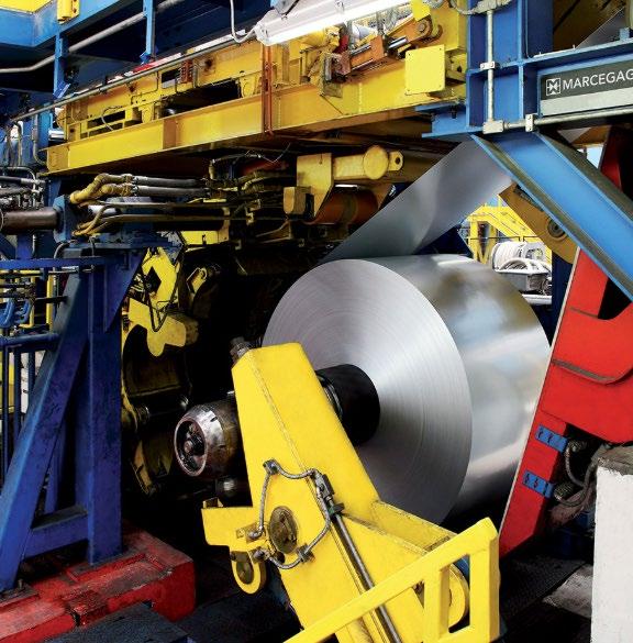
Immagine in copertina: Marcegaglia

Gestione editoriale e pubblicità Publisher and marketing office: siderweb spa sb Via Don Milani, 5 - 25020 Flero (BS) tel. 030 25 400 06 commerciale@siderweb.com - www.siderweb.com
La riproduzione degli articoli e delle illustrazioni è permessa solo citando la fonte e previa autorizzazione della Direzione della rivista. Reproduction in whole or in part of articles and images is permitted only upon receipt of required permission and provided that the source is cited.
siderweb spa sb è iscritta al Roc con il num. 26116
/ Editorial
Memorie scientifiche / Scientific papers
Laminazione / Rolling
Real-time work hardening evaluation for optimizing hot rolling schedules and power demand in HSLA steel production
Construction of heat treatment analysis model considering transformation plasticity and accuracy verification
Attualità Industriale / Industry News
Advanced load sharing control for roller straightening of long products G. Sonnenschein, K. Hashimi, R. Popp, S. Hausmann, K.
Atti e notizie / AIM news


11-13 May 2026 - Milan, Italy
EEC 2026 & EMECR 2026 will be jointly held by AIM, Italian Association for Metallurgy, in Milan on 11-13 May 2026, together with siderweb FORUM!
The EEC 2026 (14th European Electric Steelmaking conference) will cover a wide range of topics related to the production of steel using electric arc furnaces (EAFs) and other electric-based processes. The EMECR (International Conference on Energy and Material Efficiency and CO2 Reduction in the Steel Industry) has become a recognized forum for high level discussions on environmental related topics such as CO2 reduction, materials efficiency and product life cycles in the steel industry worldwide.
EEC 2026 & EMECR 2026 will provide opportunities for networking with industry leaders, researchers, and policymakers, discussing collaborative projects and partnerships. Registration fees and participation details are available at www.aimnet.it/eec2026/register/ siderweb FORUM is the 2nd edition of the biennial event organised by siderweb to discuss the present and future of Italian and European steel.
The Conferences will be enriched with an exhibition, where sponsors will be able to display new technologies and equipment. The detailed exhibiting and sponsorship packages are available at www.aimnet.it/eec2026/exhibition-sponsorship/ www.aimnet.it/eec2026
Co-organised by
Sponsored by
“Alla luce di questi ultimi sviluppi, il work hardening acquista un significato molto vicino a una variabile di stato fisicamente fondata, capace di collegare in modo coerente l’evoluzione della microstruttura, meccanismi di deformazione e risposta meccanica macroscopica.”
“In view of these recent developments, work hardeningacquiresa meaningveryclosetothat ofaphysicallygrounded state variable, capable ofcoherentlylinking microstructural evolution, deformation mechanisms, and macroscopic mechanical response.”
Il ruolo cruciale del work hardening dallo studio della plasticità alla modellistica matematica dei processi di deformazione industriali
«Il “Work hardening” è stato il primo problema affrontato dalla teoria delle dislocazioni e potrebbe essere l’ultimo a essere risolto» – A. H. Cottrell (1953).
Questa celebre frase di Cottrell sottolinea la straordinaria complessità del fenomeno del work hardening. Nel corso di oltre un secolo di ricerca, il work hardening è stato oggetto di una indagine teorica rigorosa e sistematica da parte di alcuni dei principali protagonisti della fisica dei materiali e della meccanica dei solidi. A partire dalle formulazioni fondative della teoria delle dislocazioni proposte da G.I. Taylor, E. Orowan e M. Polanyi negli anni Trenta del secolo scorso, fino ai contributi

“Work hardening was the first problem to be attempted by dislocation theory and may be the last to be solved.”
– A. H. Cottrell (1953).
This famous statement by Cottrell highlights the extraordinary complexity of the work hardening phenomenon. Over more than a century of research, work hardening has been the subject of rigorous and systematic theoretical investigation by some of the leadingfiguresinmaterialsphysicsandsolidmechanics. Starting from the foundational formulations of dislocation theory proposed by G. I. Taylor, E. Orowan, and M. Polanyi in the 1930s, up to the fundamental contributions of A. H. Cottrell, J. Friedel, A. Seeger, Z. S. Basinski, and P. B. Hirsch, the phenomenon of strain hardening has progressively been traced back to
fondamentali di A.H. Cottrell, J. Friedel, A. Seeger, Z.S. Basinski e P.B. Hirsch, il fenomeno dell’incrudimento è stato progressivamente ricondotto a una descrizione microscopica basata sulla nucleazione e successiva evoluzione di strutture molto complesse di dislocazioni e sulle interazioni tra esse. Tutti gli approcci convergono su un punto chiave: l’aumento della tensione di scorrimento è direttamente legato all’accumulo di dislocazioni e alla progressiva riduzione del loro cammino libero medio. L’evoluzione a partire dagli anni ’80 dovuta soprattutto al lavoro di Mecking-Kocks ha costituito un passaggio importante verso una impostazione modellistica del work hardening in grado di ricondurre l’incrudimento a una formulazione matematica compatta e parametrica, capace di catturare regolarità comuni tra materiali e condizioni di deformazione differenti. L’aspetto cruciale e molto pratico per l’ingegneria di processo è che il work hardening consente di descrivere il comportamento dei materiali con un numero molto ridotto di parametri, rendendo immediato il confronto tra leghe, condizioni termo meccaniche, e permettendo di estrarre similitudini robuste tra materiali apparentemente diversi. In tal modo, l’approccio Mecking-Kocks fornisce un ponte naturale tra descrizione microscopica e descrizione fenomenologica scalabile (master curve), utile per sintetizzare e trasferire conoscenza tra condizioni di processo differenti. Arrivando ai giorni nostri, nell’ambito di un progetto R&D Marcegaglia focalizzato sul processo di deformazione a caldo si è proposto una metodologia di calcolo del work hardening in tempo reale dai dati di processo in modo da rendere il laminatoio come un vero e proprio sensore virtuale dello stato microstrutturale del materiale. Con questo approccio è possibile inferire l’attivazione di fenomeni quali la ricristallizzazione dinamica, la precipitazione, le trasformazioni di fase indotte da deformazione, l’effetto della temperatura sui meccanismi di recupero e persino il cambiamento di fase. La teoria della plasticità incrementale è implementabile solo avendo a disposizione il work hardening in tempo reale e consente un’interpretazione passo passo della risposta del materiale durante ciascun passaggio di laminazione e per addestrare
a microscopic description based on the nucleation and subsequent evolution of highly complex dislocation structures and on the interactions among them. All approaches converge on a key point: the increase in flow stress is directly linked to the accumulation of dislocations and to the progressive reduction of their mean free path.
The evolution from the 1980s onward, mainly driven by the work of Mecking and Kocks, represented an important step toward a modeling framework for work hardening capable of reducing strain hardening to a compact and parametric mathematical formulation, able to capture common regularities among materials and different deformation conditions. The crucial and highly practical aspect for process engineering is that work hardening allows the behavior of materials to be described with a very limited number of parameters, enabling an immediate comparison among alloys and thermomechanical conditions, and allowing robust similarities to be extracted among apparently different materials. In this way, the Mecking-Kocks approach provides a natural bridge between microscopic description and scalable phenomenological description (master curves), useful for synthesizing and transferring knowledge across different processing conditions. Coming to the present day, within the framework of a Marcegaglia R&D project focused on hot rolling process, a methodology has been proposed for the real time calculation of work hardening from process data, with the aim of turning the rolling mill into a true virtual sensor of the microstructural state of the material. With this approach, it is possible to infer the activation of phenomena such as dynamic recrystallization, precipitation, deformation induced phase transformations, the effect of temperature on recovery mechanisms, and even phase changes. Incremental plasticity theory can be implemented only when real time work hardening is available, and it allows a step by step interpretation of the material response during each rolling pass, as well as the training of next generation generative AI models. The tangible advantages include the optimization of
modelli AI generativi di nuova generazione. I vantaggi concreti includono l’ottimizzazione della progettazione delle sequenze di laminazione (roll pass schedule) e l’identificazione delle condizioni che portano a instabilità plastica. La rilevazione precoce delle condizioni di instabilità plastica rende possibile intervenire sul processo per prevenire difetti o rotture. Alla luce di questi ultimi sviluppi, il work hardening acquista un significato molto vicino a una variabile di stato fisicamente fondata, capace di collegare in modo coerente l’evoluzione della microstruttura, meccanismi di deformazione e risposta meccanica macroscopica. Lo sviluppo di questa linea di ricerca sta producendo risultati di elevata rilevanza sia scientifica sia industriale. È stato possibile stabilire una correlazione diretta e quantitativa tra la potenza richiesta dal processo di laminazione e il livello di incrudimento del materiale, superando approcci puramente empirici. L’obiettivo scientifico ultimo di questo approccio è di ricondurre finalmente il work hardening e il coefficiente di Taylor-Quinney all’interno di un unico quadro teorico coerente, in cui l’energia di deformazione, la sua conversione in calore e l’evoluzione microstrutturale del materiale siano descritte in modo unificato. Tale integrazione rappresenta un passo fondamentale verso modelli fisicamente fondati, in grado di collegare il comportamento del materiale, i consumi energetici e le prestazioni di processo, anche su scala industriale.
roll pass schedule design and the identification of conditions leading to plastic instability. Early detection of plastic instability conditions makes it possible to intervene in the process to prevent defects or failures. In view of these recent developments, work hardening acquires a meaning very close to that of a physically grounded state variable, capable of coherently linking microstructural evolution, deformation mechanisms, and macroscopic mechanical response. The development of this line of research is yielding results of high scientific and industrial relevance. It has been possible to establish a direct and quantitative correlation between the power required by the rolling process and the level of strain hardening of the material, moving beyond purely empirical approaches. The ultimate scientific objective of this approach is to finally reconcile work hardening and the Taylor-Quinney coefficient within a single coherent theoretical framework, in which deformation energy, its conversion into heat, and the microstructural evolution of the material are described in a unified manner. Such integration represents a fundamental step toward physically grounded models capable of linking material behavior, energy consumption, and process performance, even at the industrial scale.

A. Ferraiuolo, L. Ferraiuolo
The proposed paper deal with a novel approach to evaluate the work hardening in the roll bite using the Orowan hot rolling equilibrium equation, under the assumption of a known rolling pressure distribution along the contact arc and the plane strain plasticity condition. This formulation leads to a first-order differential equation, , wherein work hardening is directly proportional to equivalent stress (related to dislocation density and underlying metallurgical complexity) and a function depending only on strain through the rolling pass geometry. The implementation of this approach in the incremental plasticity framework with iterative calculation scheme, makes it possible to reconstruct the stress-strain path of the material along the deformation history and to identify metallurgical transitions during hot rolling from deviations in the stress–strain response or changes in the work-hardening rate. The off-line predictive module is based on a machine-learning model trained on a large database comprising the results of the real-time module together with additional information on chemical composition, microstructural features, and tensile properties of the final products. A key advantage of the proposed incremental plasticity approach is its ability to drastically reduce the number of required constitutive parameters, thereby improving robustness, transferability, and suitability for real-time industrial implementation.

KEYWORDS: SMART ROLLING, WORK HARDENING, INCREMENTAL PLASTICITY, PLASTIC STABILITY, MACHINE LEARNING, TMCP;
The proposed framework is based on a first-order differential equation, d σ /d ε = Ω σ , where the work hardening rate is proportional to the equivalent stress, that, thanks to Taylor equation, is implicitly accounting for the dislocation density and underlying metallurgical state of the material. The function Ω is independent of stress and depends on strain through the rolling pass geometry, reflecting process-related rather than constitutive complexity. The range of validity of this assumption primarily corresponds to deformation regimes in which dislocation accumulation and annihilation dominate the mechanical response, as is typically the case during hot rolling under industrial strain rates. Nevertheless, the proposed methodology is not limited to the study of dislocation hardening: all relevant metallurgical phenomena such as dynamic recovery, recrystallization, or precipitation affect the evolution of the dislocation density and are therefore indirectly captured through changes in the hardening response. As a result, the framework has a broad range of applicability and enables the detection of multiple metallurgical mechanisms via their impact on
Alessandro Ferraiuolo
Marcegaglia Ravenna S.p.A., Via Baiona 141, Ravenna, Italy
Lorenzo Ferraiuolo
University of Trieste - Mathematics, Piazzale Europa 1, Trieste, 34127, Italy
the evolving dislocation state, while maintaining the simplicity required for real-time process control. To develop a robust incremental plasticity model for hot rolling, it is essential to evaluate in real time the material’s work hardening behaviour. In hot rolling, the instantaneous flow stress of the steel depends on its temperature and on the accumulated, or residual, strain from each rolling pass. By tracking how the flow stress evolves with successive deformations through a work ‐ hardening law we can accurately reconstruct the stress-strain path in real time. This capability represents the cornerstone of an incremental plasticity framework: it allows the model to update the current material state after each pass, predict subsequent hardening or softening events, and, ultimately, predict microstructural evolution and final mechanical properties under complex thermomechanical schedules. Predicting this microstructural evolution during rolling remains a huge challenge with the conventional mathematical models. Most existing approaches are based on phenomenological descriptions of the kinetics of individual mechanisms such as recrystallization or recovery and require a large number of empirical parameters. These parameters often depend on steel grade, strain path, and temperature, and must typically be determined through extensive laboratory experimentation. To overcome these limitations, we propose an innovative physically based approach that is focused on evaluating the work hardening of the workpiece within the roll gap, thereby constructing an incremental plasticity model capable of describing the stress-strain path of the material in real time throughout the rolling process. This model enables to describe the deformation history and microstructure evolution during the whole thermomechanical process. By shifting the fo-
cus from fitting numerous phenomenological parameters to capturing the physical deformation behavior directly in the roll gap, the model enables a more robust and transferable prediction of microstructural evolution. Its application to hot rolling processes (plate or strip) offers significant practical advantages. These include:
1. Real-time tracking of the thermomechanical path,
2. Detection of hardening and softening transitions,
3. Evaluation of retained strain between passes,
4. Identification of the no-recrystallization temperature,
5. Prediction of grain size evolution (both austenite and ferrite),
6. Design and control of optimized rolling schedules for advanced TMCP (Thermo-Mechanical Controlled Processing) products.
The goal of the proposed theoretical approach is to develop a general and adaptive process control framework, referred to as Smart Rolling, capable of online monitoring of the hot rolling process and a tool enabling the inference of fine metallurgical aspects of the material behavior directly under industrial processing conditions.
The proposed approach starts from the Orowan’s differential equation describing the longitudinal equilibrium of the forces operating in the roll bite. Specifically, this equation connects the radial roll pressure, S, at any point on the arc of contact with the horizontal force, f, on the corresponding plane element of unit width, perpendicular to the direction of rolling.

where R’ is the deformed roll radius, S is the radial specific roll separating force, τ is the friction force and ϑ is the angular coordinate in the roll bite. The minus sign refers to entry side and the plus sign refers to the exit side with respect to the neutral plane. The above equilibrium equation contains two unknown functions, i.e. the horizontal
pressure for unit width f, and the radial pressure on the roll surface S. To find a unique solution we need to use a second relationship between the horizontal and vertical compressive stresses given by the Huber-Mises plasticity condition:

In which σ represents the equivalent stress for compression yielding of the material, q is the normal roll pressure and h is the local thickness of the slab. As deeply described in [1] and [2] the work hardening of a workpiece
in hot rolling process, under well defined boundary condition at the roll-strip interface (sticking friction condition and plane strain), can be evaluated by the following equation:

In which σ is the equivalent stress in the material and Ω (p) is the function defined in the roll bite as:

In which the parameter p { R’,t,ε,μ } are respectively the deformed roll radius, plate thickness, strain in the roll gap, Coulomb friction coefficient. The above equation represents an explicit relationship between the work hardening properties, the global boundary conditions and the strip geometry of deformation zone. This equation recalls the Considère condition for the onset of plastic instability under uniaxial stress state. It is noteworthy that this condition is valid also for a plane strain compression stress state. This means that the plastic stability of the rolling process depends on the value of and for this reason we call it “stability function”. If the rolling process is stable, conversely if the rolling process is unstable and local necking could occur. Unstable plastic flow can be a quite critical situation during metal work processing. It is well recognised that, depending on the mode in which the necking and then failure appears, there are two distinct ways that it is noteworthy to mention: diffuse necking


beginning and local necking. In tensile tests these two stages are distinctly separated and typically the first one start when work hardening cross the actual true stressstrain curve, and it can be less critical because it is not yet localised on the specimen length. The local necking, instead, occurs on a narrow band in which the deformation can proceed only by thinning and this condition occurs when work hardening is equal to the shear strength of the material. In plane strain deformation the situation is more critical because the local necking occurs very close to diffuse necking condition, i.e. when work hardening cross the true stress value, or . The integration, on the contact arc, of the equation (3) leads to calculate the flow stress and work hardening on each mesh element of the roll bite as:
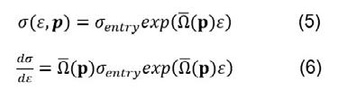

Where is the yield at entry roll bite under plane strain and is the mean integral of on the contact arc. The above equations suggest, first of all, that the work hardening depend not only by total strain but also on the stress-strain path and deformation geometry features through the function . Generally, in literature the workpiece hardening behaviour is phenomenologically


described by the Swift equation , where B and n are material parameters. It is noteworthy that the hardening behaviour predicted by the above equation and the Swift model are very close (figure 1).
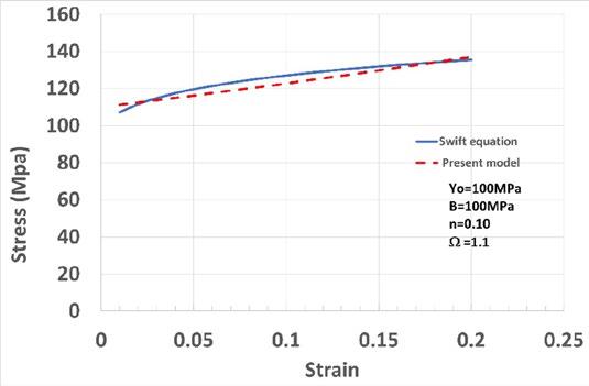
Fig.1 - Comparison between Swift hardening model and the present hardening model.
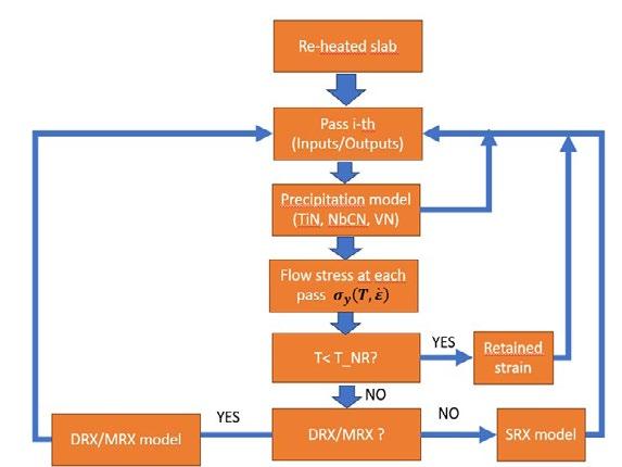
During real time operation the model, schematically represented in figure 2, allows to determine whether the material is in a condition above or below the non-recrystallization temperature (T_NR). If no recrystallization occurs (temperature is below T_NR) the material accumulates the total strain applied during the rolling pass. The microstructure continues to harden through work hardening mechanisms. If recrystallization takes place the Smart

Rolling model must further assess the type of recrystallization occurring i.e DRX or SRX. It is noteworthy that dynamic recrystallization (DRX) and Static Recrystallization (SRX) are significantly different in terms of stress-strain path in the roll bite and this produces different work hardening behaviour.
The calculation of the work hardening in real time is described in the following steps. The basic incremental equation for the i-th rolling pass is:

In which represents the equivalent stress calculated at the i-th rolling pass, is the yield stress of the material under processing at the strain rate and temperature T evaluated according the model reported in [2].
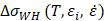
The total work hardening represents the cumulative hardening occurring in the strip/plate, after “i-th” rolling pass i.e.:


Where the first term, is the residual work hardening (due eventual retained strain from the previous passes), and the second term, , is the instantaneous work hardening of the i-th pass calculated with the equation (3). With this approach it is possible to reconstruct the stress-strain path of the workpiece in rolling process and therefore to detect, for each rolling pass, the occurrence of softening mechanisms due to dynamic/metadynamic/ static recrystallization or hardening mechanisms related to retained strain. Of course, it must be considered that
there are additional metallurgical factors affecting the hardening: these are the grain size refinement due to recrystallization and, in case of microalloyed steels, (Nb,Ti) N precipitation. Nevertheless, it must be considered that both hardening effects, in the experimental conditions tested, are significantly smaller than dislocation hardening. Introducing the parameter hardening ratio defined as the occurrence of hardening or softening at the i-th pass of the rolling schedule is evaluated according with the following conditions:


The constant HR, typically fixed in the range 0.1-0.2, represents the threshold separating the hardening and softening of microstructure. The strain path is reconstructed incrementing, if hardening is occurring in the pass, the strain of the actual pass to previous hardening passes. Conversely the strain in microstructure is equal to i-th strain pass.
In order to evaluate the microstructural evolution and final mechanical properties during hot rolling, the model requires a comprehensive set of inputs that describe both the intrinsic material characteristics and the processing conditions as: chemical composition, reheated austenite grain size, reheating temperature, rolling pass process data (among other rolling force, strain pass, strain rate, temperature).
The model yields two categories of results:
1. In-Process Microstructural Evolution
• Flow stress as a function of temperature

• Average grain size and retained strain above Tnr
• Average grain size and retained strain below Tnr
• Precipitated fraction of microalloying elements Ti, Nb, V.
• Solid solution concentrations of C and N.
2. Final Microstructure and Mechanical Properties
• During rolling: 2D distribution of austenite and ferrite grain size
• After cooling: Phase fractions and distributions (ferrite, pearlite, bainite, etc.)
• Pearlite interlamellar spacing
• Yield stress, ultimate tensile strength, and ductile ‐ brittle transition temperature.
The optimized hot rolling schedule are calculated by means of a machine learning model trained on the database containing the extensive hot rolling process data, microstructural characteristics during rolling passes, and final mechanical properties. The model is then validated and optimized to ensure accurate predictions and generalization. Therefore, the predictive part of smart rolling model allows to define the optimal rolling schedule for each
combination of steel quality and plate format in terms of:
√ Number of passes & strain per pass.
√ Roll Speed. This determines the average strain ‐ rate, torque and power needs.
√ Interpass Time. The duration between successive passes controls any microstructural transformations (e.g., static recovery, partial recrystallization) occurring between deformations.
√ Cooling Conditions. The rate of cooling in the run-out table and the coiling temperature determine the type and fraction of phase transformations (e.g., pearlite vs. bainite) that occur after the final pass.
The basic implementation of the “smart rolling” model at the hot rolling mill of Marcegaglia Plates started in offline mode and represented an experimental phase only for the post evaluation of the product quality and calculation of the microstructural evolution of the plate products. In the second industrial step, started on 2025, the smart rolling was developed with a dual mode architecture in order to operate both in real time and in off-line mode for rolling schedule calculation for each plate and with an automatic software for the reinforced training of the model parameters (figure 2-3).
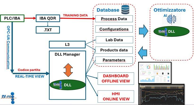
Fig.3 - Smart Rolling dual mode architecture: real time view and offline training of the model parameters.
The scope of the application of the smart rolling is to increase the plant productivity (reducing the rolling pass) and to improve the energy efficiency of the process, carrying out a proper design of the number of passes in softening stage and reducing the pass in the hardening stage where the higher work hardening and power are needed. The hot rolling plant consists of a quarto reversible mill with maximum plate width of 3000mm. The metallurgical investigation was focused on the work hardening behaviour of microalloyed steel (table 1) during hot rolling process, on the Nb effect on hindering the recrystallization kinetics and finally on the effect of retained strain of the auste-
nite phase as key parameter to evaluate the final product properties (no accelerated cooling was used). As it is well documented in literature the importance of retained strain during the hot rolling process is attributed to the effect of pancaked austenite microstructure to encourage the production of a predominantly fine polygonal ferrite forming during the austenite decomposition in the plate cooling stage. In the proposed approach the retained strain is evaluated as the cumulative strain starting from the pass from which the workpiece increases the residual hardening . With this approach the stress-strain path of the workpiece, associated to the applied hot rolling schedule,

can be reconstructed. The application of the model allows to detect quite directly the rolling passes in which softening or hardening occurs during the hot rolling process
(figure 4). In particular, the last rolling pass at which occurs softening is considered an evaluation of the temperature of no recrystallization.
Tab.1 - Steel chemical composition of the industrial plates considered in experimentation.
The main metallurgical novelty of the proposed approach is the implementation of the work hardening as an additional pillar for the design of hot rolling schedule. This power demand from the process is strictly related to the yield strength in the roll bite and this is influenced by the strain hardening behaviour, strain path, strain-rate, temperature profile and precipitation behaviour. As a further
benefit, this approach should reduce the risk of non-homogeneous deformation on the strip width and on longitudinal direction.
The power needed for hot rolling process is evaluated as the product of the torque, i.e. the moment of the tangential forces in the arc of contact about the roll axes, times the angular speed, i.e.:
P = 2 ω RR'kQG(R'/h, r)
in which k is the effective yield stress of workpiece in the roll bite (equation 5) and QG(R'/h, r) is a numeric function
accounting for the effect of the deformation geometry features on the deformation energy demand.
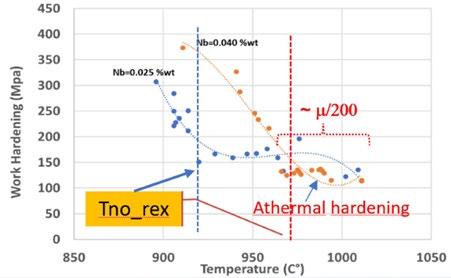
Fig.4 - a) Typical Work hardening behaviour in hot rolling; b) work hardening behaviour during hot rolling of plates with different Nb content (S355J2 steel).
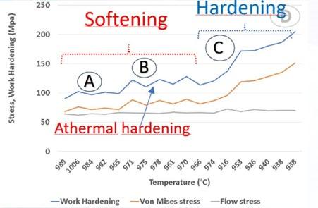
In terms of work hardening behaviour, the general trend reveals the occurrence of 4 stages. Depending on initial and final rolling temperature the stage I or IV can be less pronounced or almost absent. The first stage, occurring at higher temperature (T>960°C), is characterised by low work hardening (≤120MPa) and with the equivalent stress very close to flow stress. In this stage the softening mechanisms are dominant and the microstructure, at each pass, is refined by recovery/recrystallization. The second stage
is characterised by work hardening in the range 150-200 MPa increasing with a slow rate. In this stage it can be detected the effect of Niobium in retarding the recrystallization between two consecutive passes. In the third stage the work hardening increases with a higher rate and, depending on the chemical composition and temperature, it can achieve quite high value. Occasionally it could be detected a fourth stage characterised by a saturated or decreasing work hardening behaviour. The comparison
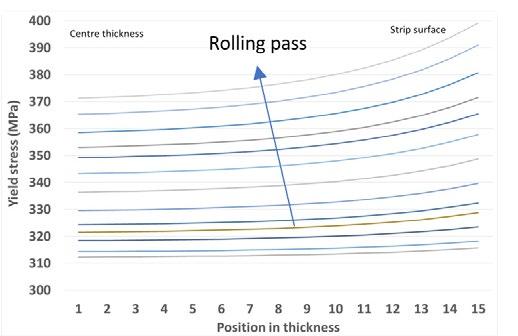
of work hardening of two plates with different Nb content (figure 4b) also reveals that, higher Nb content anticipate the stage III at higher temperature (no recrystallization temperature). The austenite grain size for each recrystallization step is calculated according with the Sellars approach [1-2-10] adopting the uniform softening method, wherein kinetics are forecasted based on a singular average microstructure with an effective strain. In case of hardening, wherein no recrystallization or recovery takes place, the strain associated to the current pass is considered as retained within the microstructure. The application of this method allows to reconstruct the evolution of the austenitic grain and to calculate the ferritic grain size, below the Ar3 temperature, accounting for the pancaking effect of the austenitic grain during hot rolling. The final step consists in the calculation of the tensile properties of the final product (yield stress and tensile strength) using
Due to strong inter-dependence of the rolling process variables, to discern the single variable effect on work hardening behaviour and on plastic stability of the global process it was developed a dedicated machine learning model trained on the database of smart rolling results. The ML model allows to get a more intuitive visualization of the work hardening behaviour when more than one process parameter is varied simultaneously. In figure 7 a)-b) and figure 9 a)-b) are shown the work hardening behaviour relevant to hot rolling process data of more than
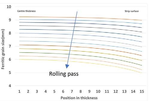
empirical equations and the ML model developed based on the historical industrial results. In the figure 5-6 are shown respectively the results of the mathematical model, in terms of ferritic grain size and yield stress for a S355J2 plate. Each plot gives the distribution along the thickness at each pass of the hot rolling schedule. The grain size is evaluated according with the method described in [1] and [2]. The soundness of the results is evaluated thanks to comparison between the calculated tensile properties (yield stress and tensile strength) with the room temperature tensile test results. The validation of the approach and the evaluation of the errors on the calculated grain size and tensile properties are under quantitative evaluation and represent a consistent part of the ongoing work to be done.
1000 plates of microalloyed steel grade S355J2. In particular, in figure 7 is shown how the work hardening is affected by a variation inter-pass time, temperature and retained strain. In figure 8 is shown how the work hardening is affected by a variation of chemical composition (Nb content), temperature and retained strain.
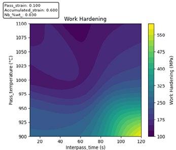
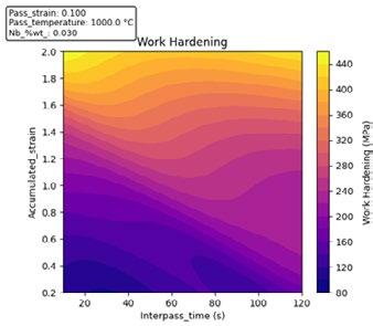
Fig.7 - a) Work hardening as a function of pass temperature and interpass time; b) Work hardening as a function of retained strain and interpass time (S355J2). a)
The aim of this approach is to design the rolling pass schedule in steady conditions avoiding processing windows in which non homogenous work hardening properties could induce a not homogeneous plate deformation and of consequence also microstructure and flatness issues. In figure 9-b) the Tno_rex becomes clearly detectable at low levels of accumulated strain when the work hardening increases from 50–150 MPa to 200 MPa or more.
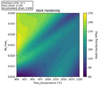
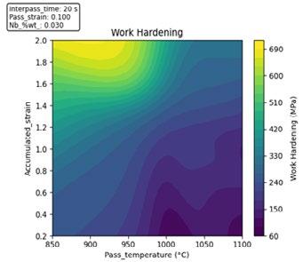
Fig.8 - a) Work hardening as a function of pass temperature and interpass time; b) Work hardening as a function of retained strain and interpass time (S355J2). a)
Plastic stability in hot rolling
As discussed above, equation (3) could provide important insights into the plastic stability of the hot rolling process. This approach opens up both theoretical and practical novel frontiers. From a theoretical perspective, equation (3) suggests that the plastic stability of hot rolling deformation is significantly affected by deformation geometry and roll-workpiece boundary conditions, particularly friction. From an application standpoint, optimizing the plastic stability associated with proper operational windows could improve the overall power demand of each rolling schedule. Achieving this ambitious goal requires optimizing both the softening and hardening passes and,
more importantly, addressing the friction behavior in the roll gap. It is well recognized that modifying the friction conditions in the roll gap represents a significant challenge because, until now, there have been no theoretical approaches to predict the behavior of the rolling process. The proposed approach aims to define the foundations for this methodology.
The general solution of the equation (3) is:
This defines an 4-dimensional hypersurface in a 5-dimensional space in which the parameters p { R’,t,ε,μ } are respectively the deformed roll radius, plate thickness, pass strain, friction coefficient.
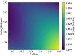
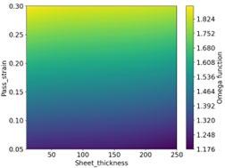
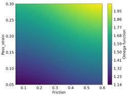
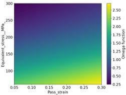
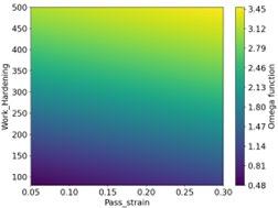
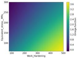
Since σ and Ω are exponentially linked, we can get more insigths by looking directly at mapping Ω (ε,p) to see how the stability function changes. To better visualize and explore this 4-dimensional object, the most practical approach is to choose two varying parameters, fix all the others, and then plot a 2D contour/color map at a fixed strain. Figure 9 presents a series of plots that illustrate how the function Ω , and consequently plastic stability, varies with changes in the main process parameters. Ω values closer to unity indicate that the plasticity conditions are near to instability, suggesting an higher sensitivity to anomaly occurrence. Notably, a lower friction coefficient has a pronounced adverse effect on plastic stability, especially at small strain reductions. Conversely an higher friction coefficient could enhance the plastic stability, thereby reducing the risk of instability and failure. These plots provide valuable insights into the relationship between friction and plastic stability. This highlights the critical role of friction in maintaining the stability of the hot rolling process. Understanding this relationship is essential for optimizing the rolling process and preventing potential issues.. This insight could be pivotal in developing strategies to optimize the rolling process, ensuring better control over the deformation and improving the overall efficiency and reliability of the operation.
In this paper, we propose a novel methodology based on incremental plasticity approach aiming to get deeper insights about into metallurgical phenomena governing the hot rolling process. The method consists in gathering the work hardening rate plot (occurrence of discontinuity, rate changes) from the real-time hot rolling process. These data were used to infer, thanks to last generation generative AI models, the most important metallurgical features such as plastic instability conditions, no-recrystallization temperature, softening/hardening contributions of each rolling pass and retained strain at each stage. The prediction of final grain size and tensile properties (yield strength and ultimate tensile strength) on the plate length and through thickness is qualitatively quite good. Quantitative validation of the methodology, together with a systematic assessment of prediction accuracy and associated uncertainties, is currently under investigation and will be the subject of forthcoming publications.
[1] L. Ferraiuolo, A. Ferraiuolo, Smart Hot Rolling Process Based on Real-Time Work Hardening Evaluation and Incremental Plasticity Theory, International Congress AISTECH 2024, Columbus, OHIO.
[2] A. Ferraiuolo, Investigation on Softening/Hardening Mechanisms in Hot Rolling Process by means of Advanced, Self-Training, Virtual Smart Sensors, International Congress AISTECH 2021.
[3] T. von Karman, On the theory of rolling, Z. Angew. Math. Mech. 5 (1925) 139–141.
[4] E. Orowan, The calculation of roll pressure in hot and cold flat rolling, Proc. Inst. Mech. Eng. 150 (1943) 140–167.
[5] D.R. Bland, H. Ford, The calculation of rolls force and torque in cold strip rolling with tensions, Proc. Inst. Mech. Eng. 159 (1948) 144–153.
[6] D.R. Bland, R.B. Sims, A note on the theory of rolling with tensions, Proc. Inst. Mech. Eng. 167 (1953) 371–374.
[7] J.M. Alexander, On the theory of rolling, Proc. R. Soc. Lond. A 326 (1972) 535–563.
[8] J.H. Hitchcock. Roll Neck Bearings. Report of ASME Research Committee (1935).
[9] F. Boratto, Effect of Chemical Composition on Critical Temperatures of Microalloyed Steels, International Conference on Physical Metallurgy of Thermomechanical Processing of Steels and Other Metals - THERMEC ‘88. Proceedings. Iron and Steel Institute of Japan, Tokyo, 1988, p. 383-390.
[10] J. J. Jonas, C. M. Sellars, and WJ McG Tegart. "Strength and structure under hot-working conditions." Metallurgical reviews 14.1 (1969): 1-24.

Il dott. Tiziano Valente ha speso la sua vita professionale nel mondo della fonderia. Tiziano Valente ha unito alla conoscenza una visione gestionale e tecnica importantissima, fattori che lo hanno portato a fare ricerca e ristrutturazioni in diverse aziende manifatturiere della provincia di Brescia e allo stesso tempo ad ottenere anche la Laurea.
Dopo queste prime esperienze professionali nel settore siderurgico ed industriale in generale, è passato a dirigere alcune aziende di pressocolata e negli anni ’80 fonda ECOTRE, l’azienda che ha condotto per oltre 40 anni, fornitrice di impianti, servizi e tecnologie d’avanguardia per il mondo manifatturiero.
Inizia così l’attività di promozione dei software di simulazione dei processi manifatturieri, con particolare attenzione al mondo della fonderia che da sempre è stata la sua passione: con la precisione e decisione che sempre lo hanno contraddistinto, aiuta questi strumenti a crescere dal punto di vista applicativo e fa in modo che diventino sempre più diffusi nel mondo industriale.
A seguito della sua scomparsa, grazie al contributo di ECOTRE Valente, l’AIM istituisce il Premio di Laurea Tiziano Valente. Il Premio include un contributo di € 3000 come riconoscimento per una tesi di laurea nel mondo del Digital Manufacturing all’interno della quale sia utilizzato un software di simulazione della colata per i processi di fonderia o acciaieria oppure dei metodi innovativi per i quali viene sfruttata l’intelligenza artificiale.
Il concorso per il premio è rivolto a studenti dei corsi di Laurea Magistrale, laureati/e presso università italiane nell’anno accademico 2024/2025 ed entro luglio 2026 per l’anno accademico 2025/2026.
Le candidature verranno prese in esame da un apposito Comitato Scientifico, che decreterà in maniera insidacabile il vincitore. La consegna del Premio avverrà in occasione del 41° Convegno Nazionale AIM.
i/le partecipanti al concorso dovranno presentare:
• curriculum vitae;
• certificato di laurea;
• autocertificazione di ottenuta autorizzazione in caso di tesi soggetta a secretazione;
• una descrizione dettagliata dal punto di vista tecnico e scientifico dell’attività di tesi svolta con l’ausilio dei software di simulazione della colata (massimo 10 pagine).
Il termine di presentazione delle domande, da trasmettersi per e-mail (info@aimnet.it) alla Segreteria AIM, è fissato al 7 agosto 2026.
per candidature e informazioni:
Via F. Turati, 8 20121 Milano
Tel. +39 0276397770 +39 0276021132
e-mail: info@aimnet.it www.aimnet.it
T. Fujisawa
In steel product manufacturing, the demand for thermo-mechanical controlled processing (TMCP) is rising to achieve various desired properties. However, uneven temperature distribution during cooling can cause shape defects. Therefore, accurately predicting thermal deformation is vital for optimizing cooling conditions. This task is challenging because thermal deformation results from complex interactions among strain, heat transfer, and phase transformations. In particular, transformation plasticity significantly influences final product quality, affecting shape and residual stresses. This study developed a thermal deformation prediction model that incorporates transformation plasticity through multi-phase transformations. The model’s accuracy and validity were assessed by comparing experimental results with simulations of camber in plate samples subjected to one-sided spray cooling. The findings revealed discrepancies between experiments and simulations that excluded transformation plasticity, whereas including it led to good agreement. This prediction method enhances the understanding of TMCP processes.
KEYWORDS: HEAT TREATMENT; PHASE TRANSFORMATION; TRANSFORMATION PLASTICITY; TMCP; CAMBER; WATER COOLING; THERMAL DEFORMATION;
In the manufacturing of steel products, the demand for thermo-mechanical controlled processing (TMCP) is steadily increasing to satisfy various property requirements. However, shape defects occur when the temperature distribution of steel products becomes uneven during the cooling process. As a result, productivity and product yield decrease. Predicting thermal deformation with high accuracy is essential for optimizing cooling conditions and improving productivity. However, it is difficult to predict thermal deformation after the cooling process because it is a complex phenomenon involving interactions among strain, heat transfer, and phase transformation [1, 2]. In particular, “transformation plasticity” is known to play an important role as it affects final product quality, such as shape and residual stresses. Previous studies have analyzed transformation plasticity considering single-phase transformations, such as bainitic and martensitic transformations [3, 4]. On the other hand, there are few analyses that consider transformation plasticity through multi-phase transformations. In this study, a thermal deformation prediction model
considering transformation plasticity through multi-phase transformations was developed to achieve high accuracy. The accuracy and validity of the analysis were evaluated by comparing experimental and simulated camber results of SUS304 and S25C plate samples after one-sided spray cooling.
The materials used in the experiment were Japanese Industrial Standards (JIS) SUS304 and S25C steel. The former does not undergo phase transformation because it is a quasi-stable austenitic steel, whereas the latter does. Table 1 shows their chemical compositions, expressed in weight percentages.
Figure 1 shows a schematic illustration of the specimen. In the experiment, square specimens measuring 200 mm on each side and 20 mm thick were used, with four thermocouples inserted at representative positions to measure temperature history. Table 2 presents the water cooling
conditions used in the experiment. The water flow density had varied to change the phase transformation and the amount of camber after cooling.
Figure 2 shows a schematic illustration of the experimental equipment. The specimen was heated to 1000°C in an electric furnace, then removed and fixed on a stand. After that, cooling water was sprayed from the spray nozzle with the shutter closed. When the specimen temperature, as indicated by the thermocouples, reached 900°C, the shutter was opened, and the specimen was cooled down to nearly 30°C. Cooling water was supplied by a pump from a reservoir tank maintained at 30°C. The water was sprayed onto the entire cooling surface through a spray nozzle mounted above the specimen, resulting in an approximately square spray area. The flow density was calculated by dividing the nozzle flow rate by the spray area. After cooling, the specimens were scanned in the widthwise direction using a laser displacement meter to evaluate the amount of camber.
Tab.1 - Chemical composition of materials. Reprinted and translated from T. Fujisawa [5] with permission of the Iron and Steel Institute of Japan. Copyright (2024) the Iron and Steel Institute of Japan.
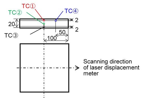
Fig.1 - Schematic illustration of specimen. Reprinted and translated from T. Fujisawa [5] with permission of the Iron and Steel Institute of Japan. Copyright (2024) the Iron and Steel Institute of Japan.
Tab.2 - Water cooling condition. Reprinted and translated from T. Fujisawa [5] with permission of the Iron and Steel Institute of Japan. Copyright (2024) the Iron and Steel Institute of Japan.
Mild cooling Intensive cooling
Nozzle model number 3/8KS0555SQ 3/8KS1760Q
Injection
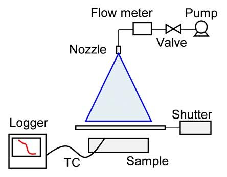
Fig.2 -Schematic illustration of experimental equipment. Reprinted and translated from T. Fujisawa [5] with permission of the Iron and Steel Institute of Japan. Copyright (2024) the Iron and Steel Institute of Japan.
In this study, the analysis software ABAQUS Standard 2018 was used. The following contents were implemented as subroutines to develop a prediction model capable of performing coupled analyses of phase transformation, temperature, and strain. Phase fractions were calculated using a method based on the TTT diagram for arbitrary temperature histories [6]. The start of phase transforma-
tion into ferrite and pearlite, which are diffusional transformations, as well as bainite, which is intermediate between diffusional and diffusionless transformations, is expressed by equation 1. The phase transformation begins when the incubation period consumption I reaches I = 1. Here, I is the incubation period, T is current temperature, t is time, and the subscript s represents the start of phase transformation in the TTT diagram.
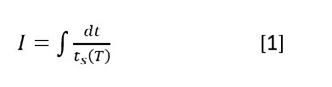
The JMAK-type isothermal transformation rate equation was used to calculate the progress of phase transformation [7], where f represents the transformation fraction, and n and k are constants. The subscripts F,P,B and eq denote ferrite, pearlite, bainite, and the equilibrium transformation rate, respectively.

The initiation and progression of martensite, a diffusionless transformation, were governed by the modified Koistinen-Marburger law [8] and implemented in the user subroutine UFIELD. Material properties, including the TTT diagram, were obtained using the material performance simulation software JMatPro. Mechanical and thermal properties were defined by considering the temperature dependence of each individual phase and were deter-
mined from the transformation ratios of each phase using the linear mixing rule.
The total strain increment was expressed by equation 3 to account for transformation plastic strain, which represents the interaction between strain and phase transformation. Here, the subscripts e,p,th,m and TP denote elastic strain, plastic strain, transformation expansion, transformation strain, and transformation plastic strain, respectively.

In particular, for transformation plastic strain in the case of multi-phase transformation, equation 4 was used based on the reports by Yanagisawa et al. [4] and Taleb et al. [9]. Here, K is the transformation plasticity coefficient, σd is the deviatoric stress, the subscript j represents each phase except austenite, and the subscript γ denotes austenite. These definitions were implemented in the user subroutine UEXPAN.

Figure 3 shows the model geometry, finite element FE mesh, and boundary conditions. To simulate the experiment in which one side of the plate was water-cooled, a cross-sectional half model was constructed by conside-
ring symmetry at the center of the width. The model consisted of a total of 2,000 elements and 2,121 nodes. The element size was 1.0 × 1.0 mm. Thermal boundary conditions were imposed on the top surface, defined by the following equation:
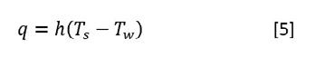
where q is the heat flux, h is the heat transfer coefficient, T s is the current temperature, and T w is the water temperature, set at 30°C. The heat transfer coefficient was de-
termined from experimental temperature history. Figure 4 shows an example of the heat transfer coefficient under intensive cooling conditions.
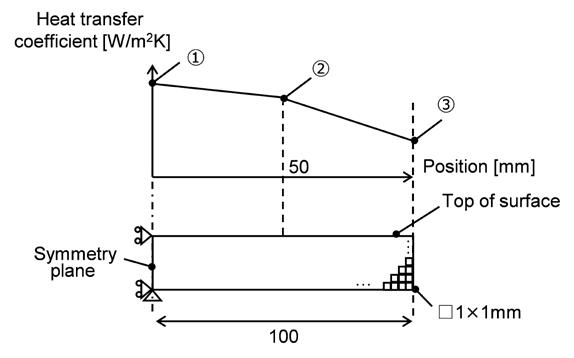
Fig.3 - Model geometry, FE mesh and boundary condition. Reprinted and translated from T. Fujisawa [5] with permission of the Iron and Steel Institute of Japan. Copyright (2024) the Iron and Steel Institute of Japan.
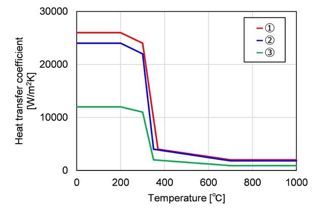
Fig.4 - Heat transfer coefficient (intensive cooling). Reprinted and translated from T. Fujisawa [5] with permission of the Iron and Steel Institute of Japan. Copyright (2024) the Iron and Steel Institute of Japan.
Figure 5 shows experimental and analytical thermal history of S25C under intensive cooling conditions as an example. It could be confirmed that the thermal history of analysis result was in accordance with that of experimental result. The obtained thermal history was similar to the typical thermal history observed when using boiling refrigerants such as water. In the initial stage of cooling, the temperature dropped slowly due to film boiling, thereafter, the temperature transitioned to nucleate boiling state and dropped rapidly. A similar thermal history was observed for SUS304, and it was confirmed that the experiment and analysis were consistent. Figure 6 shows analytical results for temperature distribution of S25C under intensive cooling at representative times. As can be seen in figure 6, the temperature on the top of surface was lower during water cooling, indicating uneven cooling. Figure 7 shows analytical results for the phase fraction distribution of S25C after cooling under intensive cooling as an example. The calculation results showed that the top of surface had approximately 90% bainite and the bottom of surface had approximately 90% ferrite and pearlite and 10% bainite, resulting in an overall transformation to three phases. On the other hand, in the case of mild cooling conditions, the proportion of ferrite in the cross section was high, at about 50 to 80%. And the remaining 20 to 50% was transformed into pearlite, resulting in an
overall transformation to two phases. From the above calculation results, it was estimated that the microstructure after cooling differs due to difference in cooling conditions even in the experiment. Note that SUS304 does not undergo phase transformation, so it remained austenite before and after cooling regardless of the cooling conditions.
As an example, figure 8 shows the experimental and analytical results for the camber of SUS304 and S25C after cooling under intensive cooling. For SUS304, since no phase transformation occurs, transformation plasticity was not considered. However, the amount of and direction of camber tended to be consistent.
On the other hand, in the case of S25C occurring phase transformation, when not considering transformation plasticity (as indicated in figure 8, without TP), the amount of camber after cooling did not match between the experiment and analysis.
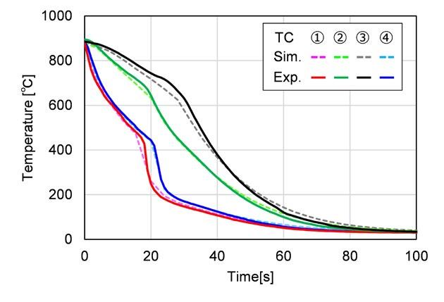
Fig.5 - Experimental and analytical thermal history of S25C (intensive cooling). Reprinted and translated from T. Fujisawa [5] with permission of the Iron and Steel Institute of Japan. Copyright (2024) the Iron and Steel Institute of Japan.
However, when considering transformation plasticity (as indicated in figure 8 with TP), the amount of camber tended to be more consistent with the experiment. It can be stated that considering transformation plasticity is important for accurately predicting the thermal deformation associated with phase transformation.
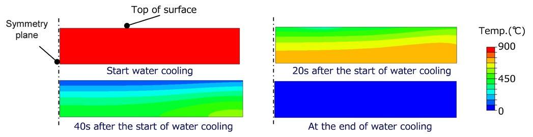
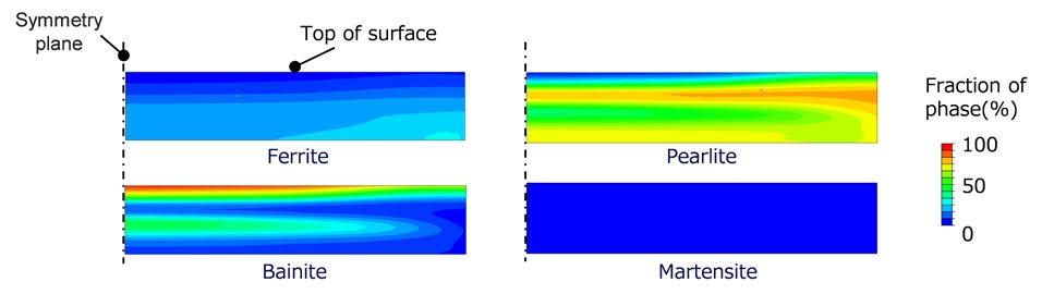
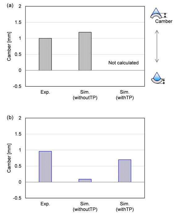
Fig.8 - Comparison of experimental and analysis camber after cooling (intensive cooling): (a) SUS304, (b) S25C. Reprinted and translated from T. Fujisawa [5] with permission of the Iron and Steel Institute of Japan. Copyright (2024) the Iron and Steel Institute of Japan.
In this study, a thermal deformation prediction model considering transformation-induced plasticity through multi-phase transformation was developed with high accuracy. The accuracy and validity of the analysis were evaluated by comparing experimental and simulated camber of SUS304 and S25C plate samples after one-sided spray cooling. As a result, when phase transformation occurs during heat treatment, neglecting transformation plasticity in the analysis leads to deviations in the predicted camber compared to experimental results. Conversely, incorporating transformation plasticity improves the agreement between predicted and experimental camber, enhancing prediction accuracy. In other words, it was confirmed that accounting for transformation plasticity is essential for accurately predicting thermal deformation. Furthermore, since the predicted camber generally
agreed well with experimental data, this analysis method is considered valid even when multi-phase transformations occur. The thermal deformation prediction method that includes transformation plasticity contributes to a deeper understanding of TMCP.
In addition, this paper including above figures (1 ~5, 8) and tables (1, 2) is reprinted and translated from T. Fujisawa [5] with permission of the Iron and Steel Institute of Japan. Copyright (2024) the Iron and Steel Institute of Japan.
[1] T. Inoue, T. Yamaguchi, Z. Wang, “Stresses and phase transformations occurring in quenching of carburized steel gear wheel,” Materials Science and Technology, 1985, vol. 1, pp. 872-876. https://doi.org/10.1179/mst.1985.1.10.872
[2] S. Denis, S. Sjöström, A. Simon, “Coupled temperature, stress, phase transformation calculation model numerical illustration of the internal stresses evolution during cooling of a eutectoid carbon steel cylinder,” Metallurgical Transactions A, 1987, vol. 18, pp. 12031212. https://doi.org/10.1007/BF02647190
[3] S. Yamanaka, T. Sakanoue, T. Yoshii, T. Inoue, “Influence of transformation plasticity on the distortion of carburized quenching process of Cr-Mo steel ring,” Journal of the Society of Materials Science, 1999, vol. 48, pp. 733-739. https://doi.org/10.2472/jsms.48.733
[4] Y. Yanagishawa, T. Hosoya, M. Minamiya, K. Saitoh, “Modeling simulation of transformation plasticity in a multi-phase transformation,” Nihon Seiko Technical report, 2019, vol. 70, pp. 32-38. https://doi.org/10.1016/j.ijmecsci.2018.08.025
[5] T. Fujisawa, “Construction of heat treatment analysis model considering transformation plasticity and accuracy verification,” CAMPISIJ, 2024, vol. 37, No. 2, pp. 350-353 (in Japanese).
[6] E. Scheil, “Anlaufzeit der Austenitumwandlung,” Archiv fur das Eisenhuttenwesen, 1935, vol. 12, pp. 565-567. https://doi.org/10.1002/ srin.193500186
[7] M. Umemoto, I. Tamura, “Continuous cooling transformation kinetics of steels,” Tetsu-to-Hagane, 1982, vol. 68, pp. 383-392. https:// doi.org/10.2355/tetsutohagane1955.68.3_383
[8] D. P. Koistinen, R. E. Marburger, “A general equation prescribing the extent of the austenite-martensite transformation in pure ironcarbon alloys and plain carbon steels,” Acta Metallurgica, 1959, vol. 7, pp. 59-60. https://doi.org/10.1016/0001-6160(59)90170-1
[9] L. Taleb, S. Petit, “New investigations on transformation induced plasticity and its interaction with classical plasticity,” International Journal of Plasticity, 2006, vol. 22, pp. 110-130. https://doi.org/10.1016/j.ijplas.2005.03.012
DOI 10.36146/2026_04_28
G. Sonnenschein, K. Hashimi, R. Popp, S. Hausmann, K. van Putten
To optimize the utilization of roller straightening machine, achieve an even and controlled distribution of the total load across the drive rollers, avoid over-dimensioning of the drives, and protect the machinery from overload, the required drive torque is distributed specifically across the drives using a control system.
A new, optimized Load Sharing Control (LSC) has been developed by interdisciplinary cooperation within the SMS group. This new LSC features the elimination of master-slave operation. As a result, it enables control when not all rolls are in operation during pulling in and out. It is independent of the process parameters (roll diameter, roll adjustment) and redistributes the total drive torque to the single drives according to a predefined pattern. Initial functional tests were conducted on forces and drive torques calculated with the aid of finite element (FE) simulations of the roller straightening processes and with available measurements. The successful implementation of the newly developed LSC in four industrial Compact Roller Straighteners (CRS®) in the fields of railway rail, medium and heavy section production conclusively demonstrates its effectiveness.
The newly optimized LSC offers benefits such as reduced total drive capacity, decreased roll wear, reduced experimental effort during commissioning and improvement of product quality. Furthermore, it can be implemented on cantilever, horizontal, vertical and combined straightening machines as well.
KEYWORDS: ROLLER STRAIGHTENING; DRIVE POWER OPTIMIZATION; DYNAMIC CONTROL SYSTEMS; PROCESS MODELLING; FINITE ELEMENT SIMULATION.
Long hot-rolled products such as beams, bars, and rails (hereafter referred to as product) tend to curve after cooling [1-4]. Roller straightening aligns these curved long products by passing them between staggered rollers, inducing controlled, repeated elastic-plastic bending. SMS group technology for roller straightening machines is the CRS® Compact Roller Straightener, typically characterized by nine, individually driven straightening rollers (figure 1).
The product enters the straightening machine on one side (left in figure 1) and is transported and straightened by the straightening rolls. During the straightening process the rolls contact the product to be straightened on two opposite sides. By adjusting the upper rolls towards the product, all straightening rolls exert a bending mo-
Guido Sonnenschein, Khaled Hashimi, Rudolf Popp, Sebastian Hausmann, Koos van Putten SMS group, Germany
ment and/or shear force on the product. The repetitive bending cycles aim to reduce the residual stresses and thereby increase the straightness. This principle and the
roller straightening machines of this type are well-established in the state of the art.
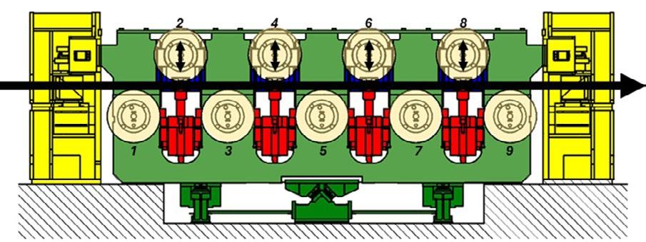
Fig.1 - SMS group Compact Roller Straightener (CRS®), typically characterized by nine, individually driven straightening rollers. The upper rollers (no. 2,4,6,8) are vertically adjustable to set the amounts of bending.
The technological challenge involves identifying the optimal roll adjustment settings to achieve maximum straightness while avoiding excessive mechanical deformation. These topics have been addressed in numerous research projects, with results reported across the literature. By way of example, without claiming completeness, the following works are briefly noted.
Alpsten’s [5] experimental and theoretical investigations showed that roller straightened (rotorized) wide flange sections have a higher resistance than their non-rotorized counterparts as a result of their lower residual stresses and improved straightness. It is suggested to use this research described to optimize the rotorizing operation regarding residual stress, straightness and column strength. Yin et al. [6] set up a theoretical framework by using spring back theory of small curvature plane bending which provides a basis for setting reasonable reduction rules to improve the straightening quality and further increase the adjustment precision as well as the flexibility of the last, adjustable, roller system. The effect of the roll settings - particularly the final roll - on the final shape of equal-leg angles as well as H-beams during roller straightening, while accounting for straightener-frame rigidity, has been investi-
gated using finite element analysis by Hayakawa [7,8]. Żak and Woźniak report comprehensively about research on the subsequent stiff and weak axis roller straightening of vignole railway rail [9-11] aiming for the reduction of the residual stresses in railway rails by changing the technological parameters of the straightening process. Numerical process models and material models were developed and validated by industrial trials. The investigations indicate the possibility of reducing stress levels in the foot down to 120 MPa, well below the maximum 155 MPa allowed by standard. While pulling in and out not all rolls are in operation resulting in considerably different residual stresses and straightness of rail near the ends compared to the straightness in the middle portion [12].
The current work, however, focuses on drive technology optimization during the roller straightening process to ensure drive torque distribution across the rollers, preventing drive over-dimensioning and machinery overload known as Load Sharing Control (LSC).
CRS with multiple individually driven rollers are fundamentally overactuated; this leads to significant torque drift. Traditional approaches to load distribution in such multi-drive systems typically rely on master-slave con-
trol architectures [13], where a single roller measured torque serves as the reference for the remaining drives. While functional in steady-state operation, this method suffers from critical deficiencies in dynamic environments such as pulling in and out phases. The master-slave approach often requires complex predefined trajectories or look-up tables [14] based on roll diameters and product geometries; and standard controllers struggle to achieve high-dynamic load redistribution without causing torque peaks that can damage the product surface or the drive train.
To overcome these limitations, this paper presents a new, optimized LSC system that departs from the master-slave paradigm. The primary novelties are threefold. First, a non-sequential, centralized intelligence considers the drive torques of all rollers currently in contact with the material, maintaining stable control even when only a subset of rollers is engaged during pulling in and out phases. Second, the algorithm achieves trajectory-free dynamic control through a speed-offset compensation mechanism that reacts in real-time to the actual total torque, making it robust against varying roll diameters and product types. Third, despite its high dynamics, the controller ensures smooth load redistribution without inducing torque peaks, distributing the total required torque
across all engaged drives either evenly or according to a user-predefined distribution, thereby protecting the machinery and improving product quality. The effectiveness of this approach is validated through both 3D finite element simulations and successful industrial implementation in heavy-section and rail production facilities.
The system is overactuated, meaning there are more actuators than necessary to control its degrees of freedom. Specifically, the rigid coupling of the rollers provides one translational degree of freedom for the product, but the system employs nine drives. Overactuation leads to coupling effects, where small deviations in roller radii or contact points create varying transmission ratios. These discrepancies, combined with decentralized speed control, result in torque drift and uneven load distribution. Figure 2 illustrates the measured drive torques during the straightening process of a wide flange beam HE400M without a mechanism to resolve overactuation. Some rollers operate near their load limits, while others experience minimal load or even work in generator mode, opposing the intended motion. This imbalance can cause inefficiencies, wear, and instability in the system.
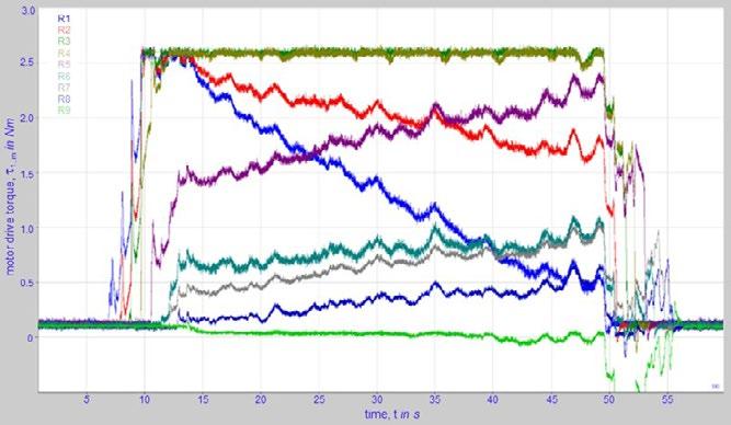
Fig.2 - Measured drive torques during the straightening of a wide flange beam HE400M without LSC.
The primary objective is to implement a load-balancing control system that ensures uniform utilization of all drives while accounting for their individual nominal torque. Most deformation work occurs in the initial straightening triangles, requiring higher drive power. Conversely, rolls at the exit side typically require less torque, which is often reflected in practice by smaller, lower-power drives. However, exit-side motors often have a power reserve
that can be leveraged to alleviate the load on front drives. Additionally, it is crucial to consider that the transferable power depends on the contact pressure between the material and the straightening roll. The control system must avoid arbitrarily increasing the torque to prevent slippage between the rolls and the material and/or localized deformation of the straightened products.
A common approach to drive torque redistribution involves measuring the torque at one roll, designating it as the master, and using it to guide the distribution of torque to the other rolls as slaves in a master-slave operation. However, this method has several drawbacks, including insufficient drive torque distribution among the rolls, leading to inefficiencies and potential overload of certain drives. Additionally, during the pulling in and out phases, the master roll might not be engaged, resulting in instabilities and uncontrolled behavior that must be managed. Furthermore, underutilization of drive motor converters can lead to unfavorable overdimensioning.
To address these issues, a centralized load-balancing controller has been developed. This controller adjusts local set speeds to compensate for transmission errors and introduces constraints to prescribe a specific load distribution. By doing so, the overactuation is resolved without altering the static translatoric speed of the product.
The newly developed LSC eliminates the master-slave operation, considering the drive torques of all straightening rolls involved in the process. The LSC is activated when contact is established in the first straightening triangle and ends when the product exits the last triangle. It distributes the total drive torque among individual drives according to a specified pattern, independent of roll diameter or roll adjustment, relying solely on actual drive torques.
Figure 3 illustrates the architecture of the Load Sharing Control system, depicting an LSC unit connected to the decentralized speed controllers of the motors, implemented via motor converters.
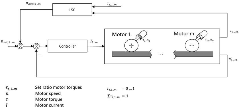
Each controller adjusts its motor speed based on a given set point (nset, 1..m), without considering the coupling with other controlled rolls. The LSC collects all measured torques from actively engaged drives and adjusts the load distribution to target ratios rτ,1..m across the individual rolls. Distribution factors determine the percentage share of drive torque allocated to each drive train, representing
the desired contribution of each motor to the total drive torque. These factors must sum to 1.0. Numerical process models can assist in pre-determining an appropriate distribution.
To achieve the target distribution, the LSC dynamically applies additional corrections to the speed set points (nadd, 1..m), compensating for transmission deviations. Once
the desired distribution is achieved, the correction values stabilize, with minor adjustments ensuring consistent and stable operation.
Main benefits of the newly developed Load Sharing Control (LSC):
• Optimized drive power: The approach minimizes the installed drive power for the straightening rolls, effectively protecting the machine from overload while ensuring high product quality for the straightened metallic goods. Energy usage is optimized for efficiency.
• Improved product property control: Enhances the prediction and management of product properties, particularly regarding residual stresses.
• Faster commissioning: Lowers the time and cost required for machine commissioning.
• Reduced wear and operating costs: Minimizes wear on the straightening rolls and reduces load on other components, such as gearboxes and couplings, leading to lower operating costs. This newly developed LSC has been filed for patent protection.
The required drive torques for predefined roll adjustments can be predicted relatively precisely over the straightening time using numerical or analytical process models, considering the pulling in and out of the product. Based on these calculations, the total drive torque of all straightening rolls can be strategically distributed among the individual rolls, significantly reducing the need for experimental calibration of the straightening machine. If necessary, a catalog of setting parameters can be created and considered in advance. However, the actual drive torques that occur in practice, resulting from the straightening process, often cannot be precisely predetermined. Therefore, the selection of distribution factors can also benefit from expert knowledge.
To facilitate initial functional testing of the control system under realistic forces and drive torques, simulations of the roller straightening processes on a CRS®-1600 are performed. The straightening of a product is numerically simulated using a transient, quasi-static, three-dimensional finite element model. The non-linear finite element
software Marc, with an implicit solver, is employed [15]. The model calculates, amongst many others, the straightening forces, roll drive torque, displacements, velocities and local magnitudes such as strains and stresses throughout the process duration [16]. This quasi-static process model does not include the dynamic behavior of the drive train. The roll drive torques calculated are the load torques from the process directly at the rollers, multiplication with the gear transmission ratio is required to obtain the motor drive torques.
A half-symmetric model is established, where the straightening rolls are defined as rigid bodies and the product as an elastic-plastic deformable body. The product is meshed with linear 8-node brick elements. The rotational motion of the rollers is transmitted as translational motion to the beam through contact, accounting for deformation (e.g., Hertzian pressure), friction, and, under certain conditions, slip. As in reality, the rollers are interconnected via the beam in the FE model as well. Throughout the process, a constant beam velocity comes into being. When calculating (total) roll drive torques is the primary objective, the rolls are defined as velocity-controlled bodies with pre-defined rotational velocities, and the drive torques are calculated accordingly. Conversely, if the aim is to verify the adequacy of roll drive torque redistribution, the rolls are defined as load-controlled bodies with pre-defined rolling torques, and the rotational velocities of the rolls, along with the translational velocity of the product, result from the calculations.
Hence, the roller adjustments determine the magnitude of the total roll drive torque required to move the beam through the rollers. A redistribution of the roll drive torques does not change the sum of all rollers drive torque, i.e. total roll drive torque.

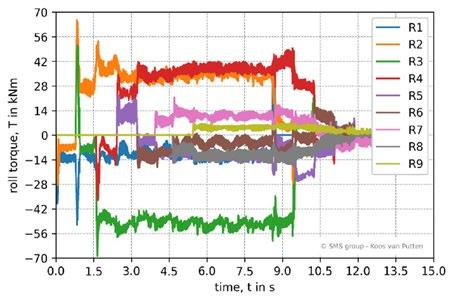
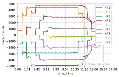
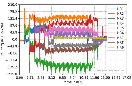
Fig.4 - In the FE model calculated roller forces and roll drive torques during the straightening.
The roller straightening of a wide flange beam HE400M, with an overstretch factor of 4.5, is simulated. The 9.38-meter beam is meshed with 88012 elements, and the process time of 14.07 seconds is divided into 4221 time increments. Additionally, the roller straightening of a bar with a 219x219 mm square cross-section and a length of 12.4 meters, meshed with 19840 elements, is modeled. The 17.08-second process time is divided into 5124 increments. Figure 4 presents the calculated straightening forces and drive torques throughout the entire straightening process, including the phases of pulling in and out.
The redistribution of the total roll drive torque has, among other methods, been tested using the square bar straightening process model. Figure 5 compares the steady state roll drive torques calculated without and with LSC. In both scenarios, the total roll drive torque is approximately 165 kNm, which is sufficient to move the beam through the rollers at a constant speed, overcoming the resistance
caused by bending. Minor deviations, less than 8%, likely arise from different averaging methods during analysis. In the straightening process without LSC, only rolls 2, 3, and 4 contribute to the product’s transportation (positive drive torque), resulting in high roll drive torques for these rolls, while the others operate in braking mode (negative drive torque). With LSC active, the prescribed distribution of 8%, 15%, 15%, 15%, 12%, 11%, 8%, 8%, 8% for rolls 1 through 9, respectively, is achieved, ensuring that all rolls contribute to the transportation of the product.
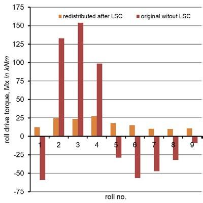
- Steady state roll drive torque distribution for 219x219 mm square bar straightening without and with LSC.
The effectiveness of the newly developed LSC is conclusively demonstrated through four successful implementations in industrial CRS® systems, particularly in the fields of railway rail, medium, and heavy section production. At this point, the positive impact of LSC on industrial straightening vignole railway rails [17] is highlighted as an example and as representative of its benefits for other profiles.
Figure 6 illustrates the measured motor drive torques during the straightening of a vignole railway rail without LSC active, recorded with the aid of IBA analyzer [18]. In this state, all additional speed setpoints are zero, leading to a heterogeneous distribution of the total motor drive torque across the individual drive axes. Specifically, roll 3 exhibits the highest torque contribution at approximately 1150 Nm. Rolls 2, 4, and 5 contribute around 400 Nm each, while roll 6 adds 200 Nm. Rolls 1, 7, and 8 operate in braking mode, registering torques of approximately -500 Nm, -200 Nm, and -400 Nm, respectively. This suboptimal torque distribution compromises efficiency in terms of both drive power and energy consumption, consequently leading to increased wear and higher operating costs.
Figures 7 and 8 display the measured motor drive torques during the straightening of vignole railway rails with the newly developed LSC active. The primary distinction between the measurements displayed in figure 7 and figure 8 lies in the predefined distribution factors. The straight-
ening process depicted in figure 7 aims to distribute the total motor torque almost equally across all drives. In contrast, the configuration shown in figure 8 assigns a smaller torque share to rolls located at the machine’s exit compared to those at the entry.
The roll adjustment settings remain consistent with those used in figure 6. By dynamically adapting the additional motor speed setpoints, the system successfully achieves the predefined target torque distribution. Following this initial adaptation, the additional setpoints largely stabilize, reflecting the inherent transmission deviations between the rolls. This phenomenon is particularly evident in figure 8, where the distribution factors have been intentionally altered. Once the target distribution is achieved, the additional motor speed setpoints converge to similar values for both tested distribution scenarios.
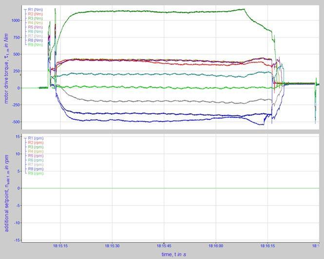
Fig.6 - Additional setpoints (bottom) and motor drive torque (top) during straightening of vignole railway rails without LSC.
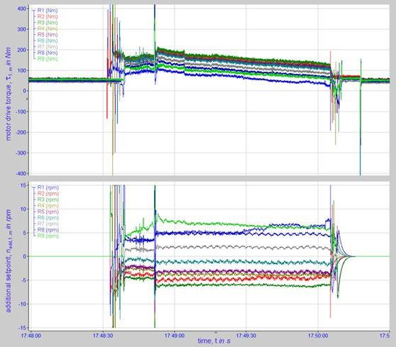
Fig.7 - Additional setpoints (bottom) and motor drive torque (top) during straightening of vignole railway rails with LSC. Distribution factors 9%, 11%, 11%, 11%, 11%, 11%, 12%, 12%, 12% for rolls 1 through 9, respectively.
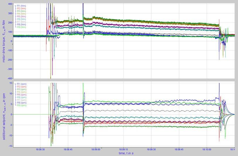
Fig.8 - Additional setpoints (bottom) and motor drive torque (top) during straightening of vignole railway rails with LSC. Distribution factors 9%, 15%, 15%, 15%, 11%, 11%, 8%, 8%, 8% for rolls 1 through 9, respectively.
An advanced Load Sharing Control (LSC) system for roller straightening machines has been developed and successfully implemented in three industrial CRS® in the fields of railway rail, medium and heavy section production. The new LSC ensures uniform utilization of all drives while accounting for their individual nominal torque. It overcomes limitations of traditional master-slave systems by enabling independent control and intelligent torque redistribution across all drive rollers, regardless of process parameters or partial roll engagement during the pulling in and out phases.
Validated through FE simulations and four successful industrial applications in railway rail, medium, and heavy section production, the LSC demonstrably optimizes load distribution. This leads to significantly reduced total drive capacity, decreased roll and component wear, lower operating costs, and enhanced product quality. By ensuring balanced drive utilization, the LSC streamlines commissioning and contributes to more efficient and reliable straightening processes for a wide range of long products.
[1] F.D. Fischer, G. Schleinzer, “Residual stress formation and distortion of rail steel,” in: Handbook of residual stress and deformation of steel, eds. G.Totten, M. Howes, T. Inoue, (2002), ASM International Publishers, 424-436.
[2] L. Chen, M. Yang, “Effects of cooling on bending process of heavy rail steel after hot rolling,” Metallogr. Microstruct. Anal., 5 (2016),196-206. DOI:10.1007/s13632-016-0272-2
[3] Y. Yong Zang et al., “The analysis of temperature field and residual stress distribution during H-beam cooling process,” Adv. Mat. Res., 194-196 (2011), 20-25. https://doi.org/10.4028/www.scientific.net/AMR.194-196.20
[4] X. Zhao et al., “Research on the out of square of H-beams,” Mat. Sci. Forum, 749 (2013), 473-478. https://doi.org/10.4028/www. scientific.net/MSF.749.473
[5] G. Alpsten, “Residual stresses, yield stress, and the column strength of hotrolled and roller-straightened steel shapes,” IABSE reports of the working commissions, 23 (1975), 39-59. https://doi.org/10.1016/j.istruc.2023.105828
[6] J. Yin et al., “Principle of multi-roller straightening process and quantitative resolutions of straightening strategies,” J. Iron Steel Res. Int., 21(2011), 9, 823-829. https://doi.org/10.1016/S1006-706X(14)60148-5
[7] K. Hayakawa, “Finite element analysis on roller-straightening process of equal leg angles,” Tetsu-to-Hagane, 95 (2009), 11, 43-49. DOI:10.2355/tetsutohagane.95.773
[8] K. Hayakawa et al., “Finite element analysis on roller straightening process of H-section beams,” Steel Research International, 1 (2008), 506-512.
[9] S. Żak, D. Woźniak, “Controlling the state of residual stresses in railway rails by modifying pass design of straightening rollers,” Arch. Metall. Mater. 68 (2023), 1, 57-70. DOI:10.24425/amm.2023.141473
[10] S. Żak, D. Woźniak, “Influence of vertical straightener roller shape on residual stress level in railway rails,” Arch. Metall. Mater. 69 (2024), 1, 245-255. DOI:10.24425/amm.2024.147815
[11] S. Żak, D. Woźniak et al., “Numerical modelling of rail straightening in a nine-roller vertical and nine-roller horizontal straightener system,” Processes 13 (2025), 646-663. https://doi.org/10.3390/pr13030646
[12] S. L. Srimani, A. C. Pankaj, J. Basu, “Analysis of end straightness of rail during manufacturing,” Int. J. Mech. Sci. 47 (2005), 1874-1884. https://doi.org/10.1016/j.ijmecsci.2005.07.005
[13] M. Ebadpour et al., “Modeling and synchronized control of dual parallel brushless direct current motors with single inverter,” Computers & Electrical Engineering, 70 (2018), 229-242. https://doi.org/10.1016/j.compeleceng.2017.08.016
[14] J. Kabziński, Ed., Advanced control of electrical drives and power electronic converters, Springer Cham, 2016.
[15] Hexagon, software: Marc and Mentat.
[16] K. van Putten, T. Daube, “Investigation of the roller straightening process for long products,” In: Proceedings of the 12th Simufact Round Table, Bamberg, 2010. DOI:10.13140/RG.2.2.35991.89769
[17] DIN EN 13674-1 Railway applications – Track-Rail – Part 1: Vignole railway rails 46 kg/m and above; German version EN 136741:2011+A1:2017
[18] iba AG, software: ibaAnalyzer
R. Conte
QSP-DUE direct casting and rolling technology allows three production modes: coil-to-coil, semi-endless, and full endless. These modes enable the production of various steel grades and strip formats, meeting end-user needs. The maturity of the technology is evidenced by concrete applications. The process offers a wide product mix, catering to various market needs, with perspective towards automotive exposed sector with dedicated features and production strategies. At the same time the commitment to sustainability is evident through the electrification efforts, setting new standards for high-quality, sustainable steel production, driving innovation, and meeting diverse market demands.
KEYWORDS: QSP-DUE; SLAB; ROLLING; STRIP THICKNESS; AUTOMOTIVE EXPOSED;
The QSP-DUE process developed by Danieli represents a significant advancement in high-quality hot-rolled coil production. This direct slab casting and rolling process is rapidly gaining market share due to its competitiveness and ability to meet diverse market requirements. Over the past 30 years, Danieli has continuously innovated the Quality Strip Production (QSP) family, developing the Danieli Universal Endless (DUE) layout.
QSP-DUE offers three production modes: coil-to-coil, semi-endless, and full endless. Full endless mode allows direct rolling of cast products without division into slabs, making it ideal for ultra-thin commercial grades. Coil-tocoil mode provides flexibility, with slabs cut by the pendulum shear and processed individually. Semi-endless mode balances efficiency and customization, with jumbo slabs cut and rolled, then separated into coils by a highspeed shear. These modes enable the production of various steel grades, thicknesses, and widths to meet diverse end-user needs.
Global references confirm the success of the Danieli Universal Endless layout Thanks to its proven performance and flexibility, QSPDUE technology has been successfully implemented
by leading steelmakers worldwide. These installations demonstrate the reliability, productivity, and versatility of the Danieli Universal Endless layout across different production targets and operating conditions.
The following references highlight the real-world achievements and technological excellence of QSP-DUE in various regions.
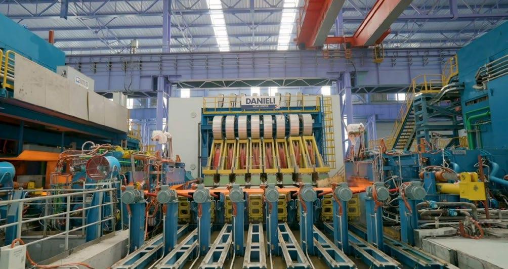
Hoa Phat Dung Quat Steel Joint Stock Company / Vietnam
The Dung Quat QSP plant, operated by Hoa Phat Dung Quat Steel Joint Stock Company, has a design capacity of up to 3.9 million tons of steel per year, and it is one of the most productive plants operating in the world. To date, the QSP has produced over 13 million tons of hot-rolled coils, maintaining high quality. Operational efficiency allowed the achievement of 6 m/min casting speed and a sequence length of over 28 hours. The caster processed 50 heats without interruption, covering a total length of 7,342 meters, and achieved a production output of 13,040 tons in one day, with an average throughput of more than 470 tons/hour.
Class 1 quality hot-rolled coils maintain a stable rating of 97.5%, showing excellent strip surface quality and coil shape. QSP operations are consistently stable and reliable,
even for thin gauges as low as 1.2 mm. New, high-value products developed include the weather-resistant grade SPAH with a strip thickness of 1.6 mm, which meets the required quality and mechanical properties for container-making applications.
Yukun Iron & Steel Group Co., Ltd. (Yukun) started up a new DUE plant in 2024 to produce up to 4.6 Mtpy of hotrolled coils, setting a new world record for Danieli’s in-line casting and rolling technology. The DUE line produces strip thicknesses from 0.80 to 25.4 mm and widths between 900- and 1,500-mm. Casting records have been set on the Danieli-patented DySen caster: 145-mm-thick slabs have been regularly produced, using a 152-mm mould. 165-mm-thick slab rolling was also tested. Endless rolling has been established, reaching the mini-
mum design thickness of 0.8 mm thick strip within the first seven campaigns from the beginning of the endless production. Coils showed excellent surface quality, precise geometric dimensions, and uniform microstructure and properties.
This followed the production of thicknesses of 25 mm in the same line, something unique in the world.
Within 10 days of the DUE plant start, Yukun marketed and sold premium-quality HRC products.
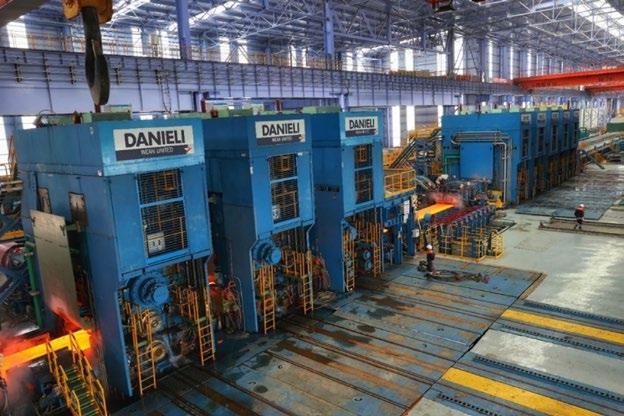
Shougang Jingtang United Iron & Steel Co. Ltd. / P.R. China
Shougang Jingtang United Iron & Steel Co. Ltd. (SGJT) confirmed its trust in Danieli’s technology by ordering the world’s first Danieli Universal Endless (DUE®) plant, which has been operating at full capacity since 2019, exceeding the nominal capacity of 2.1 Mtpy. The caster reached a speed of 6 m/min for low-carbon grades, with
stable casting conditions. Up to 37 heats were cast in 24 hours, equivalent to around 7,800 tons, with casting sequences exceeding 16 hours of continuous operation.
Endless production represents up to 97% of each casting and rolling sequence, with steady-state rolling conditions enabling thin-gauge production. Over 90% of QSP-DUE output is less than 2.0 mm thick, with over 50% ranging from 1.5 mm down to the recent plant record of 0.70 mm.
The QSP-DUE process allows a wider product mix to respond to various market needs, especially in the automotive sector. Today, QSP-DUE operators can produce and deliver grades with superior mechanical properties and surface quality. The focus is on automotive applications, particularly for exposed panels. These grades are used in complex components, adding value, and yielding higher profit margins. Advanced high-strength steels (AHSS) are increasingly in demand, projected to exceed 85% of the automotive market in the future. AHSS grades include crack-sensitive types like peritectic, Dual Phase, Complex Phase, Martensitic, and TRIP steels.
Several innovations developed by Danieli in recent years have been available to ensure the widest possible product mix. The funnel-shaped mould normally used in thin-slab casters deforms the shell during solidification, making it unsuitable for high surface-quality grades. Danieli has designed a flat mould for high-speed casting, improving fluid dynamics and eliminating chemistry limitations. Last
year this mould was tested at high casting speed on a thin slab caster, showing excellent results in terms of surface quality and sequence duration.
Exposed grades are generally prone to clogging, which is counteracted by argon injection into the mould and the use of a quick-change submerged entry nozzle (SEN). These practices are now possible in the QSP-DUE process, thanks to increased mould thickness, a slim SEN design, and robotic operations that ensure high repeatability and safety.
Additionally, the argon-loaded flow in the mould is controlled by the MM-EMB+S, which combines two different technologies: an AC brake/accelerator, widely used in conventional slab casters, and the DC device, adopted in thin slab casting for a long time. The MM-EMB+S enables a wide variety of operating modes, including mould stirring, particularly useful for several reasons: temperature homogenization, inclusion floatation, prevention of inclusion entrapment and reduction of gas bubble entrapment.
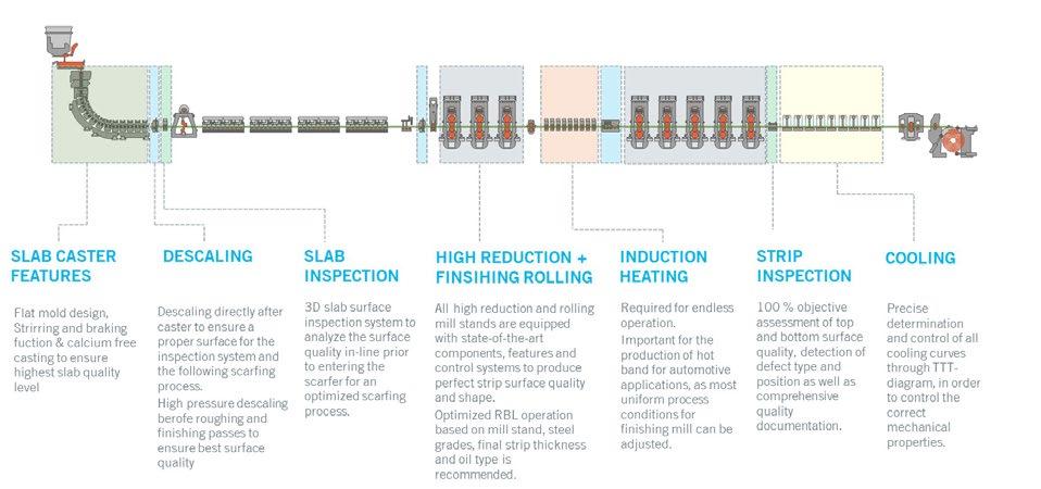
Fig.4 - Equipment specifically designed for automotive-exposed quality requirements.
QSP-DUE features three descaling points: the first at the caster exit, the second just before the first roughing stand, and the last right before the first finishing mill stand. The combination of the three devices ensures coils are free from defects related to scale imprinting. Two surface in-
spection systems are foreseen, one at the caster exit and the second prior to the downcoiler area, providing immediate feedback on strip-surface quality and its compliance for auto-exposed applications.
To achieve the highest standards of surface quality and
optimize the production of exposed panels, scarfing might be required. The scarfing process is performed using oxygen-fueled linear torches to remove a thin layer of material along with surface defects, such as cracks, non-metallic inclusions, or surface irregularities that can compromise the hot-strip surface quality. The precision of this process is vital to minimizing material loss while achieving a defect-free surface. The scarfer is integrated into the production process, conditioning slabs while hot to maintain the energy-saving approach of the QSP-DUE. The scarfer operates at the same productivity as the casting machine and hot strip mill, ensuring that all the slabs produced in a sequence are surface conditioned.
Compared to the conventional route, the DUE process reduces energy consumption by 70%, leading to a 90%
reduction in CO2 emissions. While QSP-DUE is already an environmentally friendly technology, further electrification of processes that currently rely on fossil fuels— such as tundish and SEN preheating, and the gas-fired tunnel furnace—can reduce direct CO2 emissions to zero. The primary source of direct emissions in the DUE process is the tunnel furnace, which allows coil-to-coil and semi-endless production modes, in addition to the full endless production mode, significantly broadening the product mix. Additionally, the tunnel furnace serves as a buffer during work roll changes in the rolling stands, enabling longer production sequences with consistent surface quality. A clear advantage from an OpEx perspective.
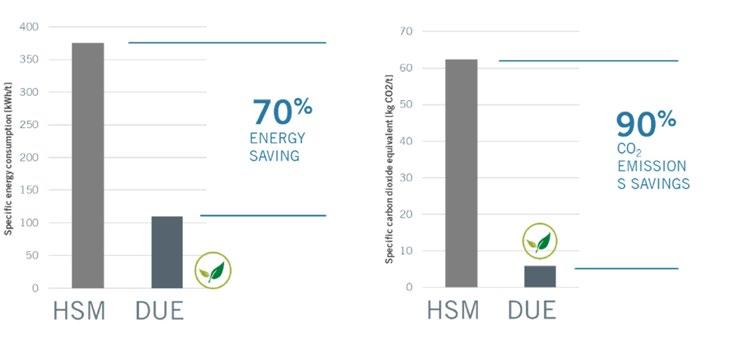
Reducing emissions requires enhancing efficiency and rethinking the heating process. One effective strategy is to minimize heat losses by replacing the currently used water-cooled rolls with dry rolls, which can yield energy savings of approximately 25 to 30%. Transitioning the tunnel furnace toward full electrification necessitates a comprehensive overhaul of its components. Given the slab thickness, longitudinal flux induction heaters have been selected to maximize electrical heating efficiency. The layout of the electric tunnel furnace includes a combination of sections with induction heaters and sections equipped with electrical resistance.
QSP-DUE is a mature technology that has demonstrated advantages over the conventional route in terms of energy efficiency and its ability to cover an extremely wide product mix, as proven by actual results. As the industry evolves, QSP-DUE sets new standards for high-quality, sustainable steel production, driving innovation and meeting diverse market demands.
J. Lindwall, H. Magnusson, L. Almquist Pessoa
A hot rolled steel strip that seemingly comes out as flat after the final rolling pass might potentially end up with flatness issues after it has been coiled. It is not easily understood which mechanisms in the coiling process are causing flatness issues. It is known from a material perspective that a combination of high stresses and temperatures can cause stress relaxations and creep deformations when the time in this state is long enough. A hot coiled steel strip at 600°C with a mass of 27 tonnes will take long time to cool down and it is uncertain whether stress recovery and creep behaviour have an impact on the final flatness. To investigate this, a three-dimensional thermo-mechanical finite element model with a creep material model is used to simulate the influence of creep deformations on final shape. It is, on one hand found that a relatively complex stress profiles are developed through the strip thickness when coiling, with compressive and tensile stresses beyond the yield stress, and that the tensile stresses recover unsymmetrically on one side of the strip midplane. On the other hand, is it also found that the creep deformations are only a fraction of the plastic deformations caused by the mechanical work during the coiling process. Hence, it is concluded that creep mechanisms play no, or possibly a marginal role in the shape of the final shape. Whereas stress relaxations result in a stress neutral profile in the coiled state, which may cause shape variation after uncoiling and post processing.
KEYWORDS: HOT COILING; CREEP; RELAXATION; FE-MODELLING; STRIP ROLLING; FLATNESS;
INTRODUCTION: HOT COILING AND STRESS RELAXATION
To reach the expected product quality of steel strips there is a continuous interest to understand and to predict the possible causes for flatness defects. Defects can arise during rolling, at cooling at the run-out table, or at the coiling process with cooling to room-temperature. There are different types of flatness issues that can develop during rolling, common are development of longitudinal waves, as illustrated in figure 1. Mainly, these waves arise under unfavourable rolling when the affected section becomes more processed than the rest of the cross-section of the strip. The additional work elongates the material more and the material needs to go somewhere, and the result is repeatable buckles.
In this study, interest is on the evolution of stresses and potential flatness issues that can occur when the hot steel coil is cooled to room temperature. Coiling as a process has been studied in the past by different groups. Modelling the thermo-mechanical aspects of coiled steels is complex and many different aspects should be consid-
ered, as discussed in detail in [1]. Many studies in literature focus on the evolution of residual stresses for spring back analysis at decoiling such as [2]. Some few studies focus on the coiling process itself, trying to solve the complex temperature distribution in the coil during cooling, capturing variations along length and width of strip [3-8]. None of these studies have included the role of creep during slow cooling from high temperature, which can cause deformation of the coil and potential flatness issues.
The interest in this work is to investigate is to investigate if plastic deformation through creep can cause sufficient material deformation because of uneven cooling such that these defects appear by simply coiling at high temperature, even if the strip was flat beforehand. The study includes a detailed description of the stress and strain developments of the entire strip up to the coiling and models how these stresses and strains change during the hot cooling at 600°C to room temperature.
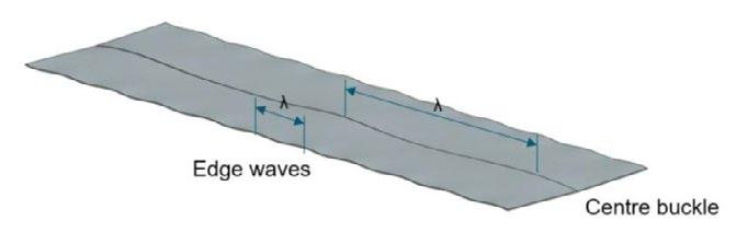
As a starting point in the study, the so called Finbeam material model was used to fit Gleeble data, Schill et al. [9]. This model has been implemented in LS-Dyna and can capture the material response at hot-working conditions including deformation hardening and relaxation. Typical material testing parameters for hot-working conditions are 850-1250°C, and strain-rates 0.1-30 s-1. In this study, interest is at lower temperatures around 600°C, and much lower strain-rates (or creep rates), which require additional material testing but also possibly a new material model.
The original material model, which is based on an Estrin-Mecking type of model with some modifications [10],
used a Zener expression to capture the role of strain-rates and temperatures on the dependent stresses, being yield stress, peak (tensile) stress, and steady-state stress. This allows for accurate interpolation and extrapolation in these quantities when doing simulations. Since this model was originally adapted for hot-rolling conditions with higher temperatures and deformations rates, the accuracy at low temperatures in the creep regime is to be concluded in this work. The interest is to follow how the yielding point can be reduced by potential creep. The expressions for yield stress and Zener parameter are according to below, Z is the Zener expression R as gas constant and T as temperature in Kelvin.
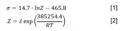
Models for creep are typically expressed the other way around, with strain-rate (creep rate) expressed as function
of stress and temperature. Using the above two expressions, the strain-rate can be expressed as:

The parameters in the first term in equation 3 relates to the stress in MPa and the second term describes an activation energy J/mol. This model was never intended to work for creep conditions, but since its exponential relation between stress to strain-rate it is on the same form as many creep equations [11], especially for lower temperatures when creep is typically of importance for steels. In the above conversion, the yield stress has been used. Yielding is per definition the onset of deformation, and by deforming at slow deformation rates the creep stress should approach the yielding point. For faster
deformation, additional work-hardening might occur, but this is not included here.
The requirements to describe creep is a model that should give a similar relation between strain-rate and stress, from relatively fast deformation down to creep conditions. The built-in material model MAT188 in LS-Dyna was selected, which uses a Garfalo-type of Sinh-expression as shown in equation below. Other possibilities are Norton-type of creep laws which have a power-law to stress, and thereby too weak relation between stress and strain-rate.

An advantage with the above equation is that it is very similar to Eq. (3), as the Sinh-expression follows an exponential expression as long as the stresses are large, which they are at low temperatures (here defined as 600ºC or lower). By comparing the two expressions, the following parameters are derived:
- m = 1 (should be exponential at low temperatures)
- A = 1.15∙1014 s-1
- Q = 46338.0 J/mol
- B = 0.06802 MPa-1
Slow strain tensile testing was used to feed the creep material model with data. The material used in the study is a hot roller strip with yield stress around 350 N/mm which can be coiled at 600°C in a range of thicknesses. Slow tensile testing was applied with deformations rates
of relevance for both creep and faster deformation. Testing temperatures were chosen with respect to coiling, at 400-600°C. It was assumed that even lower testing temperatures below 400ºC are similar to room temperature properties.
The results from the evaluated slow-strain tensile tests are given in figure 2. Stresses are shown versus displacement measured in millimeters. The testing covers temperatures 400, 500 and 600ºC, and strain-rates from 10-6 to 0.2s-1. The trials with slowest strain-rate were interrupted before rupture, since the material had reached a steadystate creep stress needed to feed the material model. The results are according to expectation, that stresses increase with higher strain-rate and lower temperature.
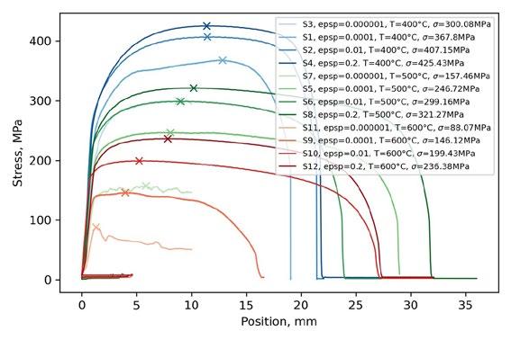
Fig.2 - Stress as function of position (in mm), for all the tests. The trials with slowest strain-rates were interrupted after steady-state conditions had been reached.
A coil was recorded with a thermal camera directly after coiling and continued for 33 hours while it was left to cool. The recording was then analysed in a software where markers were placed strategically on the frame as shown
in figure 3. Markers 1-12 was placed on one side of the coil, mark 13-15 on the outer layer and mark 16-18 on the inside. These markers were later used to calibrate a model to simulate the temperature evolution in a representative solid body.
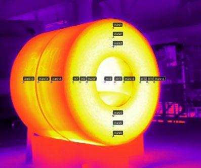
The temperature evolution was modelled using a 2-dimensional axis-symmetric model with anisotropic thermal conductivity in the radial and axial direction. The modelling domain is shown in figure 4. Material data was estimated using JMatPro. The radial conductivity is highly limited due to the small gap between each layer, consisting of oxide scales and air gap, and was modelled by applying a factor that reduced the values. The factor could not easily be estimated as it depends on the thermal conductivity and thickness of the oxide and gap between each layer, contact pressure, thermal shrinkage, etc. [7].
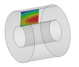
Ultimately, this depends on the elastic material properties and the contact pressure because of tensioning during coiling. The factor then becomes a unique value for each position in the coil and changes over time. A simplification was done by calibrating a constant value to provide a good fit to the measured temperature histories. The resulting value used in the simulations was 0.3, meaning that the thermal conductivity in the radial direction was 30% of the values in the solid material. The material density was assumed constant and equal to 7758.79 kg/m3
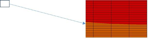
- Coil model for temperature simulation and mesh resolution.
The stresses and plastic deformation developed during the coiling process was modelled in two separate models: one model for the stretching in the length direction together with bending over the pinch rolls, and another model for the coiling with bending on the increasing coil radius. The stress state from the first model was used as initial state to the second model using the interface_ springback keyword in LS-Dyna. The final stress state after coiling was later used as an initial state for the creep simulation. Symmetry conditions made in possible to only model one half of the strip/coil, from the centreline to one edge. This simplification was done in all models.
The strip was modelled with shell elements with a thickness of 4 mm having five integration points in the thickness direction. Meaning that there will be a resolution of the stress through the thickness as there will be compressive and tensile stresses in the strip.
An initially stress-free strip segment was pre-tensioned with a coiling force and bent over a rigid cylinder, shown in figure 5. The rigid cylinder represents the lower pinch roll with a diameter of 235 mm. The strip tension of 75794 N (half because of symmetry) was applied to the front of the strip at an angle that represented the increasing coil radius. The tail was constrained with a strip velocity of 5.0 m/s, which is an assumed mean value of the rolling speed
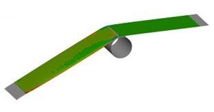
in the final pass. The bending naturally causes compressive stresses on the bottom surface and tensile stresses on the top surface. The tension causes and average tensile stress in the length direction. The sum of these stresses gives the actual stress state in any position in the 3D space.
The final stress state from the pre-tensioning was applied as an initial state in the coiling simulation. The front elements were fixed to a rigid spiral-shaped body at its smallest radius. The spiral was rotated with an angular velocity that corresponded to the coiling velocity of 5.0 m/s, see figure 5. Hence, the rotation velocity gradually decreased as the radius increased to maintain a periphery velocity of 5.0 m/s. When the strip elements and the spiral elements came into contact, they were permanently tied, assuming no slipping between the two parts. The tail was constrained with a point load equal the strip tension 75794 N (half because of symmetry) and constrained to a horizontal plane to limit additional bending (simulating firm alignment with the pinch rolls).
When the simulation was completed, a dynain file was automatically created using the interface_springback keyword. This creates a part file with the deformed geometry and the current stress and strain state. This file was later used as input to the stress recovery and creep simulation with the temperature history simulated earlier as an external load.
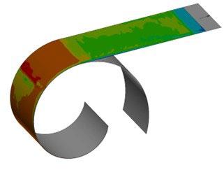
Simulation of the stress relaxation was done by combining the thermal simulation of the temperature history and the final state of the coiling simulation. The creep model was a transient implicit structural model only and the temperature history was applied with the keyword load_thermal_binout. The temperature was mapped to the geometry by the nodal ID’s. Thus, it was absolutely necessary that the radial and axial position of each node in the deformed body corresponded to the exact same position of the same node ID’s in the thermal model, that was rotationally symmetrical. This was achieved by modelling with the same number of elements in the radial direction in the thermal model as the number of elements in the length direction in the mechanical model. The spiral shaped body increase the radius linearly such that all elements land on the designated radial position.
The simulation was completed when the temperature reached values well below 200°C, which took about 24
hours. The time steps were automatically adopted but never longer than 100 seconds or such that the maximum temperature change was no higher than 0.01°C/time step. The stresses, effective creep strain etc. were computed every time step and stored to a data file in a frequency of 120 seconds for external postprocessing.
The temperature history by the thermo-camera recording and the simulation are shown in figure 6. Solid lines belong to the side of the coil where one edge of the strip is seen layer by layer. The dashed lines belong to the side where the tail of the strip is seen. The model parameters calibrated to fit the measurement on the firsts (mark 1-3). The temperature readings by mark14 and mark15 drops more quickly than other values, assumed because of a looser contact on the last lap, and therefore with poor thermal conductivity in the radial direction.
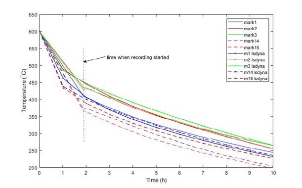
Fig.6 - Temperature history at selected position of the coil; measured and simulated.
When the strip is under tension and bent in the pinch rolls, it experiences compressive stresses and plastic deformation on the underside and tensile stresses end plastic deformations on the upper side as presented by the blue curves in figure 7. The mean stress and the stress at the neutral plane are positive as expected by the pulling force in the length direction. Much of the stresses swich between compressive and tensile when it is coiled, as seen
by the red lines in the same figure. The radius of the coil is much larger than the radius of the pinch roll and therefor, the strip is “bent back” to a straighter state, yet curved. The stresses reach the yield stress, and the strip becomes plastically deformed in tension and compression, right graph in figure 7. Because of the limited hardening at the coiling temperature, the stress doesn’t increase much beyond the yield stress.
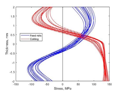
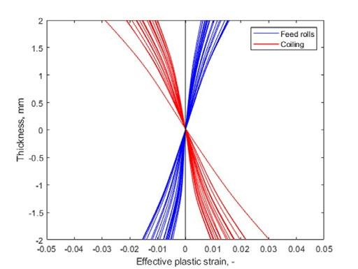
Fig.7 - Stress (left) and effective plastic strain (right) development during tensioning in pinch rolls and coiling. Each line represents the value through thickness at a location along the centreline of the strip. Values go from blue to red.
The built-in stress relaxes during the time when the coil cools down from the coiling temperature. Figure 8 shows the stresses and effective plastic strains at a low temperature, as they change from the initial coiling state shown in Figure 7. The potential/driving force for stress relax-
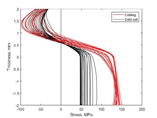
ation is high in the beginning when both the stresses and temperatures are high. Eventually, the rate reduces, and the stress stabilizes at roughly ± 50 MPa. Even with the reduced stress state, the change in plastic strain is only marginal as shown in the right graph in figure 8.
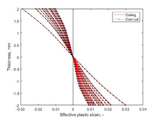
Fig.8 - Stress (left) and effective plastic strain (right) evolution during cooling of the hot coil. Each line represents the value through thickness at a location along the centreline of the strip. Values go from red to black.
The material changed shape to a very small amount during cooling due to creep, as shown in three layers in the strip thickness in figure 9. The total creep strain acts as a plastic deformation and could potentially lead to flatness is-
sues. However, the maximum creep strain was computed to 4.9×10⁻⁴ which is very low as compared to the effective plastic strain by the mechanical deformation during coiling. As a reference, the effective plastic strains by mechanical work were around to 2×10⁻² at most.
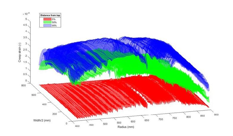
Fig.9 - Total creep strain during cooling of the hot coiled strip. Each plane represents a cross section along the thickness, i.e. 5% from the top is the outer surface (convex side) and 95% from the top is the inner surface (concave side), 50% is the centrum plane through thickness.
The rate at which the plastic strains recovers is shown in figure 10. As indicated by the scale, the rate is low, about 1.0×10⁻⁷ at most, and decreases quickly because of the decreasing temperature and stresses.
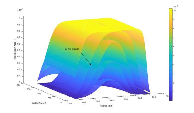
Fig.10 - Plastic strain rate in strip in steps of 30 min directly after coiling.
The resulting total creep strain during cooling is only a fraction of the effective plastic strain developed during coiling. This suggests that the creep strain will have no, or potentially a very little effect on the shape of the strip.
Thus, creep is no factor to consider when it comes to flatness issues during coiling. In other words, all shape changing deformations are caused by the mechanical work during the coiling process. Nevertheless, the stresses within the strip that are close to the flow stress have
recovered during the cooling. It was only on the bottom half of the strip that the stresses recovered from values around 150 MPa to about 50 MPa. The upper half did not recover much at all as the initial stress state in compression was already low. The noticed stress recovery is not expected to have additional effects on the flatness as the values are well below the yield stress in cold conditions.
Additional plastic deformations are applied during uncoiling to straighten the strip. The stresses required to unfold the strip, and make it flat, would have to be higher than the yield stress to have any permanent effects. Therefore, it is not possible to predict if the residual stress from the coiling has any effect at all on the final product. Likely, the uncoiling process itself will act as a levelling process.
We suggest that the simulation results conclude that creep has not effective impact on the flatness of the strip during coiling. The stress variations along the width of the strip on the other hand, caused by the mechanical deformation during coiling, indicate that there might be variation of residual stresses after uncoiling. It is uncertain whether this relatively small stress variations can have an impact on the final flatness. If this mechanism is of interest to investigate, it is suggested that the complete coiling and uncoiling is simulated with flow stress data at relevant temperatures and strain rates at coiling and room temperatures.
[1] V. Sattinger, A. Kainz, K. Schörkhuber, L. Aigner, K. Zeman. (2013). “Calculation of mechanical and thermal influences during coiling of hot strip”, XII International conference on computational plasticity - Fundamentals and applications. COMPLAX XII. E. Oñate, D.R.J Owen, D. Peric, B. Suárez (Eds.). https://www.researchgate.net/publication/296680155_Calculation_of_Mechanical_and_Thermal_ Influences_During_Coiling_of_Hot_Strip
[2] F. P. Amado, T. Gurova. (2025). “Prediction of residual stress after cold rolling and coiling process”, The Journal of Strain Analysis for Engineering Design, 60(1), 49-58. https://doi.org/10.1177/03093247241273805
[3] B. Yang, J. Scholler, E Montazerozohour, S. Grosseiber, A. Seyr, B, Linzer. (2025). “Advanced coil cooling model incorporating layering and interface effects of strip windings”, ISIJ International 65(11), 1717-1724.
[4] M. Dai, Y. Hu, Y. Hao, P. Qiu, H. Xiao. (2025). “Analysis of temperature and stress fields in the process of hot-rolled strip coiling”, Metals 2025, 15(2), 111. https://doi.org/10.3390/met15020111
[5] R. Raj, J. B. Wiskel, M. J. Gaudet, D. G. Ivey, H. Henein. (2024). The effect of non-uniform skelp temperature on X70 steel coil cooling. Ironmaking & Steelmaking: Processes, Products and Applications. 2024;0(0). doi:10.1177/03019233241291653
[6] M. Karlberg. (2011). “Modelling of the temperature distribution of coiled hot strip products”, ISIJ International 51(3), 416-422. DOI:10.2355/isijinternational.51.416
[7] M. Karlberg. (2016). “Thermo-mechanically coupled isotropic analysis of temperatures and stresses in cooling of coils”, ISIJ International 56(10), 1808-1814. DOI:10.2355/isijinternational.ISIJINT-2016-073
[8] S. Witek, A. Milenin. (2018). “Numerical analysis of temperature and residual stresses in hot-rolled steel strip during cooling in coils”, Archives of civil and mechanical engineering 18, 659-668. https://doi.org/10.1016/j.acme.2017.11.002
[9] M. Schill, J. Karlsson, H. Magnusson, F. Huyan, N. Safara, J. Lagergren, T. Narström, F. Johansson. “Simulation of hot plate rolling using LS-Dyna”. Presented at the 13th European LS-Dyna conference 2021, Germany.
[10] N. Haghdadi, D. Martin, P. Hodgson. (2016). “Physically-based constitutive modelling of hot deformation behavior in a LDX 2101 duplex stainless steel”. Materials & Design 15, 420-427. https://doi.org/10.1016/j.matdes.2016.05.118
[11] S. R. Holdsworth, M. Askins, A. Baker, E. Garboldi, S. Holmström, A. Klenk, M. Ringel, G. Merckling, R. Sandström, M. Schwienheer, S. Spigarelli. (2008). “Factors influencing creep model equation selection”, International journal of pressure vessels and piping 85(12), 80-88. https://doi.org/10.1016/j.ijpvp.2007.06.009
Andrea Manente, Annalisa Fortini, Marialaura Tocci
Principi teorici e pratici dell’analisi termica applicata alle leghe di alluminio
Principles and applications of thermal analysis for aluminium alloys

› INTRODUZIONE
› SCHEDE TECNICHE
› Leghe da fonderia e esempi di modifica
› Esempi di affinazione
› Leghe speciali
› Leghe madri
› Leghe da deformazione plastica
› CASI DI STUDIO
› Effetto della variazione del Si sulla solidificazione
di leghe Al-Si e Al-Mg
› Effetto della modifica con Sr e Ca della lega AlSi10Cu1Mg
› Effetto della modifica con Na su leghe Al-Si all’aumentare
del tenore di Si
› Segregazioni di fase eutettica in getti ottenuti mediante
colata in bassa pressione o pressocolata
› Segregazioni di fase eutettica in componenti
realizzati in lega AlCu4
› Confronto tra una lega EN AB 42100 ottenuta da riciclo
e la corrispondente lega primaria
› Applicazione dell’analisi termica per valutare l’efficacia
di maniche esotermiche e isotermiche
› Valutazione dell’umidità di stampi in terra
› Cricche a caldo su getti fusi in conchiglia
› Esempi di affinazione di leghe Al-Mg e Al-Zn
Il nuovo volume edito da AIM è disponibile per l’acquisto!
Un manuale che offre una panoramica su aspetti teorici e pratici dell’analisi termica delle leghe di alluminio, attraverso schede tecniche e casi di studio reali.
Il volume è destinato a ingegneri, tecnici di fonderia, ricercatori e studenti che desiderano comprendere e sfruttare appieno le potenzialità dell’analisi termica per ottimizzare la qualità e le prestazioni delle leghe di alluminio nella pratica industriale. ordina la tua copia su
Caratteristiche dell’opera
Anno di pubblicazione: 2024
ISBN: 9788898990368
Formato: A4
Foliazione indicativa: 386 pagine
Lingua: Italiano/Inglese
Rilegatura: brossura cucita filo refe
Prezzo di copertina: Euro 100,00
› Effetto di una affinazione non ottimale su getti ottenuti con lega Duralite
› Cricche a caldo su getti ottenuti tramite colata in conchiglia
› Analisi termicha della lega AZ91HP usata per produrre getti tramite
colata in bassa pressione

Master Master in Progettazione stampi
MODULO 2
La progettazione dello stampo con riferimento al Manuale della difettologia AIM
15 e 16 aprile 2026 - via Zoom + 29 aprile 2026 - Brescia presso UniBs
MODULO 3
I difetti nei getti pressocolati con riferimento al Manuale della difettologia AIM
20 e 21 maggio 2026 - via Zoom + 27 maggio 2026 - Vicenza presso UniPd – DTG
>> SCOPRI DI PIÙ


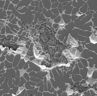
Giornata di Studio
Il ruolo decisivo delle Tensioni Residue sulle prestazioni delle leghe industriali
Caratteristiche, criticità, strumenti di misura e metodologie di analisi
Milano c/o Fast - 6 maggio 2026
>> SCOPRI DI PIÙ
EEC 2026 - EMECR 2026 Conferences - siderweb FORUM
4th European Electric Steelmaking conference, 5th International Conference on Energy and Material Efficiency and CO2 Reduction in the Steel Industry and the 2nd edition of the biennial event organised by siderweb to discuss the present and future of Italian and European steel Milano - 11-13 May 2026
>> MORE INFO
Giornata di Studio
Caratterizzazione di prodotti da processi additive manufacturing Casi pratici e studi di difettologie
Rovereto c/o Trentino Sviluppo - 21 maggio 2026
>> SCOPRI DI PIÙ
MICROSCOPIA ELETTRONICA IN SCANSIONE (SEM)
V EDIZIONE
Lecco c/o Politecnico di Milano - 26-27 maggio 2026
>> SCOPRI DI PIÙ
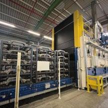

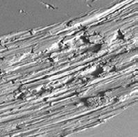

Giornata di Studio Trattamenti termici delle leghe di alluminio Dal fornitore al cliente Provaglio d’Iseo (BS) c/o Gefran - 10 giugno 2026
>> SCOPRI DI PIÙ
Giornata di Studio Celebrazione 70° Centro Daccò Ferrara – 12 Giugno 2026
>> SCOPRI DI PIÙ
Giornata di Studio
ECNDT 2026 | Failure Analysis & NDT Verona - 18 giugno 2026
>> SCOPRI DI PIÙ
Tribologia c/o Laboratorio Te.Si. dell'Università degli Studi di Padova Rovigo - 24-25 giugno 2026
>> SCOPRI DI PIÙ
Summer School Digitalization & AI in Metallurgy Udine – 28-29-30 giugno – 1 luglio 2026
>> MORE INFO


Giornata di Studio Superleghe di nichel
Reggio Emilia - 7 luglio 2026
>> SCOPRI DI PIÙ
Summer school “Environmental Assisted Cracking” Milazzo (ME) - 5-9 July 2026
>> MORE INFO
WCCM 2026
The 4th World Congress on Condition Monitoring Milano, Italy - 25-27 August 2026
>> MORE INFO
41° Convegno Nazionale AIM Progettiamo il futuro tra ricerca e innovazione Brescia - 9-11 settembre 2026
>> SCOPRI DI PIÙ
5th International Conference on INGOT CASTING, ROLLING & FORGING
Bardolino, Verona - 13-15 October 2026
>> MORE INFO
Il centro Metallurgia fisica e Scienza dei materiali si pone trasversalmente alla base dei contenuti proposti da altri CT di AIM, molto più verticalizzati su specifici settori della produzione o utilizzo dei materiali metallici.




Il centro ha infatti come obiettivo primario la promozione della conoscenza dei principi di base per la comprensione dei materiali metallici, ovvero la metallurgia fisica e la scienza dei materiali. Esse sono fondamentali per comprendere il comportamento dei materiali metallici, sia durante il loro uso sia nella loro produzione e trasformazione. Non solo: costituiscono gli elementi chiave da cui partire per sviluppare nuove soluzioni di materiali e processi. Il centro favorisce la diffusione non solo di quanto noto e consolidato, ma cerca anche di offrire scorci su nuovi materiali e applicazioni traendo spunto dalla forte presenza accademica all’interno del centro.
Gli obiettivi del centro sono sviluppati attraverso tre linee di azione principali:
• la riproposizione, in veste sempre nuove e aggiornate, di corsi base su temi di fondamentale importanza;
• l’organizzazione di giornate di studio dedicate ad argomenti specifici poco conosciuti ma di alto valore tecnico o scientifico, per favorire con la diffusione della conoscenza occasioni di interscambio e cross-fertilization;
• la collaborazione con altri centri di AIM, portando il contributo del centro a manifestazioni più focalizzate.
Esempi di queste azioni, limitandoci agli eventi più recenti, sono state:
• La giornata di Studio “Idrogeno: tra realtà attuale e le opportunità per il futuro”, che si è svolta il 18 novembre 2025, online, in collaborazione con
Presidente: Paola Bassani
CNR ICMATE, Lecco
Vicepresidente: Riccardo Donnini
CNR ICMATE, Milano
Segretario: Alberto Castellero
Università di Torino, Dipartimento di Chimica
i CT Corrosione, controllo e caratterizzazione dei prodotti e Materiali per l’energia. La giornata ha offerto una visione a tutto campo del tema “Idrogeno” accostando interventi di ampio respiro sullo stato dell’arte dell’uso dell’idrogeno e della ricerca su questo vettore energetico, a interventi sull’attuale impiego dello stesso.
• La giornata di Studio “Tra resistenza a fatica e tenacità. La risposta delle leghe metalliche agli sforzi dinamici” svoltasi da poco (2 marzo 2026) in presenza a Milano presso il Centro Congressi FAST, che continua una felice serie biennale di corsi/ giornate di studio rivolte all’approfondimento del comportamento meccanico dei materiali metallici in specifiche condizioni. Questa edizione ha offerto un’importante occasione di approfondimento riguardo agli effetti di sollecitazioni e ambiente sulle proprietà delle principali leghe industriali e ai fattori che determinano le proprietà di resistenza a fatica e tenacità delle leghe, ovvero la loro capacità di sostenere carichi di tipo dinamico.
• Il workshop “Additive Metallurgy”, che si è tenuto il 21-22 gennaio 2026, presso Campus Bovisa Politecnico di Milano in collaborazione con il CT Metallurgia delle polveri e tecnologie additive e quello di Metalli leggeri. Il workshop ha rappresentato la naturale evoluzione del Corso “Additive Metallurgy”, nato dall’esigenza di fornire contenuti scientifici legati ai fondamenti dei processi di additive manufacturing applicata ai materiali metallici, svincolandosi dai contenuti più tipicamente tecnologici o di processo di altre iniziative in ambito additive manufacturing.
Rivolgendoci al futuro, a breve si svolgerà la quinta edizione del Corso “Microscopia Elettronica in Scansione - SEM” per metallurgisti, il 26-27 maggio prossimi a Lecco. La microscopia elettronica a scansione è oggi uno strumento essenziale non solo per la ricerca, ma anche per lo sviluppo industriale e il controllo qualità, perché permette di osservare dettagli microstrutturali impossibili da ottenere con altre tecniche. Il corso offre l’opportunità di conoscere
i principi di base della microscopia in scansione, fondamentale per pianificare correttamente le analisi ed evitare errori interpretativi. Non mancherà il contributo del centro al Convegno Nazionale di AIM, che si svolgerà dal 9 all’11 settembre a Brescia, con una sessione dedicata a spunti innovativi nell’ambito della ricerca sui materiali metallici.

L’Associazione Italiana di Metallurgia (AIM) e la Société Française de Métallurgie et de Matériaux (SF2M) hanno avviato una nuova fase di collaborazione con la firma di un Memorandum of Understanding volto a rafforzare i rapporti tra le due associazioni. All’incontro hanno partecipato, per AIM, il presidente Silvano Panza e il segretario generale Federica Bassani; per SF2M il presidente Jean-Luc Béchade, il vicepresidente Xavier Sauvage, il segretario generale Michelle Salvia e il responsabile delle relazioni internazionali, Stefan Drawin.
Partendo dalla volontà di sviluppare legami più stretti tra le due comunità scientifiche, l’obiettivo condiviso è rafforzare il settore della metallurgia e dei materiali a livello nazionale ed europeo, attirando al contempo giovani ingegneri e ricercatori verso questa disciplina, attraverso la partecipazione alle attività delle due associazioni.
AIM e SF2M hanno inoltre concordato di promuovere lo scambio reciproco di informazioni sugli eventi organiz-

zati, attraverso i rispettivi siti web e di sostenersi nell’organizzazione di grandi conferenze internazionali, anche attraverso l’invito di relatori. L’accordo prevede anche la partecipazione incrociata di esperti a webinar, conferenze e iniziative formative, come scuole estive, oltre alla promozione di scambi tra i Comitati tecnici di SF2M e di AIM.
Con questa intesa, AIM e SF2M compiono un passo significativo verso una cooperazione strutturata tra la comunità metallurgica italiana e quella francese, con l’ambizione di rafforzarsi sul piano europeo e di sostenere lo sviluppo delle future generazioni di scienziati e ingegneri dei materiali.
Questo accordo è arricchito dal compimento dell’ottantesimo anno di attività di entrambe le associazioni – SF2M lo scorso anno, mentre AIM si appresta a celebrarlo questo 2026 – a garantirne la lunga tradizione e l’autorevolezza nel campo metallurgico.

di Linda Castagnini e Lorenzo Iannarelli
Menzioni onorevoli della prima edizione del concorso “La Metallurgia a fumetti” 2025

11-12-13 maggio 2026
Milan Marriott Hotel, Milano
siderweb FORUM è l’appuntamento biennale di siderweb che riunisce i protagonisti dell’industria siderurgica italiana ed europea per discutere il presente e il futuro del settore.
Per la seconda edizione, l’evento cresce in format, durata e attrattività per il pubblico: si svolgerà in contemporanea con EEC 2026 (14th European Electric Steelmaking Conference) ed EMECR 2026 (5thInternational Conference on Energy and Material Efficiency and CO2 Reduction in the Steel Industry), due conferenze internazionali organizzate da AIM Associazione italiana di Metallurgia
SIDERWEB FORUM EEC | EMECR
• Scenari geopolitici
• Mercati globali
• Transizione energetica
• Innovazione
> Scopri il programma!
• Tecnologie per la decarbonizzazione
• Processi innovativi per EAFs
• Efficienza energetica e riduzione della CO2
L’agenda aggiornata dei convegni è disponibile su siderweb.com/siderweb-forum
Oltre ai convegni e alle conferenze, sarà presente anche un’area espositiva dedicata alle aziende del settore. Guarda gli espositori ON BOARD
CO-ORGANIZED BY
Normativa / Standards
Norme pubblicate e progetti in inchiesta (aggiornamento al 31 marzo 2026)
Norme UNSIDER pubblicate da UNI nel mese di marzo 2026
UNI EN ISO 10059-1:2026
Prodotti refrattari sagomati densi — Determinazione della resistenza alla compressione a freddo - Parte 1: Prova di riferimento senza interposizione di spessori
UNI EN 15542:2026
Tubi, raccordi e accessori di ghisa sferoidale — Rivestimento esterno di malta cementizia per tubi — Requisiti e metodi di prova
UNI EN 12680-2:2026
Fonderia — Controllo mediante ultrasuoniParte 2: Getti di acciaio per componenti sottoposti a sollecitazioni elevate
UNI EN ISO 18203:2026
Acciaio — Determinazione della profondità degli strati induriti
UNI EN ISO 8894-2:2026
Materiali refrattari — Determinazione della conduttività termica - Parte 2: Metodo del filo caldo (disposizione parallela)
UNI EN ISO 26203-1:2026
Materiali metallici — Prova di trazione a elevata velocità di deformazione - Parte 1: Sistemi a barra elastica
UNI EN ISO 21809-2:2026
Industrie del petrolio e del gas, compresa l’energia a basse emissioni di CO2 — Rivestimenti esterni per tubazioni interrate o sottomarine usate nei sistemi di trasporto via tubo
- Parte 2: Rivestimenti a singolo strato a base di resine epossidiche applicate per fusione
UNI EN 12680-3:2026
Fonderia — Controllo mediante ultrasuoniParte 3: Getti di ghisa a grafite sferoidale
UNI EN 15979:2026
Prove su materie prime ceramiche e materiali ceramici — Determinazione diretta della frazione di massa delle impurezze in polveri e granuli di carburo di silicio mediante spettrometria di emissione ottica con eccitazione ad arco in corrente continua (DCArc-OES)
UNI EN ISO 14577-5:2026
Materiali metallici — Prova di penetrazione strumentata per la determinazione della durezza e dei parametri dei materiali - Parte 5: Metodo di prova mediante indentazione strumentata dinamica in campo elastico lineare (DIIT)
UNI EN ISO 5014:2026
Prodotti refrattari sagomati densi e isolanti — Determinazione del modulo di rottura a temperatura ambiente
UNI EN 10253-2:2026
Raccordi per tubazioni da saldare di testaParte 2: Acciai non legati e acciai ferritici legati con requisiti specifici di controllo
UNI EN 15991:2026
Prove su materie prime ceramiche e materiali ceramici — Determinazione diretta della frazione di massa delle impurità in polveri e granuli di carburo di silicio mediante spettroscopia dell’emissione ottica da plasma accoppiato induttivamente con vaporizzazione elettrotermica (ETV-ICP-OES)
Norme UNSIDER ritirate con sostituzione da UNI nel mese di marzo 2026
UNI EN ISO 26203-1:2018
Materiali metallici - Prova di trazione a elevata velocità di deformazione - Parte 1: Sistemi a barra elastica
UNI EN 993-6:2019
Metodi di prova per prodotti refrattari a forma densa - Parte 6: Determinazione del modulo di rottura a temperatura ambiente
UNI EN 12680-3:2012
Fonderia — Controllo mediante ultrasuoniParte 3: Getti di ghisa a grafite sferoidale
UNI EN 15979:2011
Prova dei materiali ceramici primi e di base — Determinazione diretta di frazioni di massa delle impurità in polveri e granuli di carburo di silicio tramite OES per eccitazione d’arco DC
UNI EN ISO 18203:2022
Acciaio — Determinazione della profondità degli strati induriti
UNI EN 15991:2016
Prova dei materiali ceramici e relative materie prime — Determinazione diretta della frazione massica delle impurità in polveri e granuli di carburo di silicio mediante spettroscopia dell’emissione ottica da plasma accoppiato induttivamente (ICP OES) con vaporizzazione elettrotermica (ETV)
UNI EN 12680-2:2005
Fonderia — Controllo mediante ultrasuoniParte 2: Getti di acciaio per componenti sottoposti a sollecitazioni elevate
UNI EN 10253-2:2021
Raccordi per tubazioni da saldare di testa -
Parte 2: Acciai non legati e acciai ferritici legati con requisiti specifici di controllo
UNI EN ISO 21809-2:2014
Industrie del petrolio e del gas naturale — Rivestimenti esterni per tubazioni interrate o sommerse utilizzate in sistemi di tubazioni per il trasporto - Parte 2: Rivestimenti a singolo strato a base di resine epossidiche applicate per fusione
UNI EN 15542:2008
Tubi, raccordi e accessori di ghisa sferoidale — Rivestimento esterno di malta cementizia per tubi — Requisiti e metodi di prova
UNI EN 993-15:2005
Metodi di prova per prodotti refrattari formati densi - Parte 15: Determinazione della conduttività termica per mezzo del metodo del filo caldo (disposizione parallela)
UNI EN 993-5:2019
Metodi di prova per prodotti refrattari a forma densa - Parte 5: Determinazione della resistenza alla frantumazione a temperatura ambiente
Norme UNSIDER pubblicate da CEN e ISO nel mese di marzo 2026
EN ISO 14720-2:2026
Testing of ceramic materials — Determination of sulfur in non-oxidic ceramic raw materials and ceramic materials - Part 2: Inductively coupled plasma optical emission spectrometry (ICP-OES) or ion chromatography (IC) after burning in the oxygen flow (ISO 147202:2026)
EN ISO 14720-1:2026
Testing of ceramic materials — Determination of sulfur in non-oxidic ceramic raw materials and ceramic materials - Part 1: Infrared measurement methods (ISO 14720-1:2026)
EN 15542:2026
Ductile iron pipes, fittings and accessories — External cement mortar coating for pipes — Requirements and test methods
Progetti UNSIDER messi allo studio dal CEN (Stage 10.99) – aprile 2026
prEN ISO 13680 rev
Oil and gas industries including lower carbon energy “Corrosion-resistant alloy seamless products for use as casing, tubing, coupling stock and accessory material” Technical delivery conditions
EN 10253-4:2025/prA1
Butt-welding pipe fittings - Part 4: Wrought austenitic and austenitic-ferritic (duplex) stainless steels with specific inspection requirements
Progetti UNSIDER in inchiesta prEN e ISO/DIS – aprile 2026
prEN – progetti di norma europei
prEN ISO 12135
Metallic materials — Unified method of test for the determination of quasistatic fracture toughness (ISO 12135:2021, including corrected version 2022-08)
prEN 10219-1
Cold formed welded steel structural hollow sections - Part 1: Technical delivery conditions
prEN 10380
Finished non-alloy and alloy steel products for structural use
prEN 10210-1
Hot-finished steel structural hollow sections - Part 1: Technical delivery conditions
prEN 10250-3
Open die steel forgings for general engineering purposes - Part 3: Alloy special steels
ISO/DIS – progetti di norma internazionali
ISO/DIS 24695
Oil and gas industries including lower carbon energy — The effects of High Voltage DC interference to buried pipelines — Measures to be implemented
ISO/DIS 15136-3
Oil and gas industries including lower carbon energy — Progressing cavity pump systems for artificial lift - Part 3: Downhole-drive systems
Progetti UNSIDER al voto FprEN e ISO/ FDIS – aprile 2026
FprEN – progetti di norma europei
FprEN ISO 19901-7
Oil and gas industries including lower carbon energy — Specific requirements for offshore structures - Part 7: Stationkeeping systems for floating offshore structures and mobile offshore units (ISO/FDIS 19901-7:2026)
FprEN ISO 19901-2
Oil and gas industries including lower carbon energy — Specific requirements for offshore structures - Part 2: Seismic design procedures and criteria (ISO/FDIS 19901-2:2026)
FprEN ISO 6892-2
Metallic materials — Tensile testing - Part 2: Method of test at elevated temperature (ISO/ FDIS 6892-2:2026)
FprEN 10253-1
Butt-welding pipe fittings - Part 1: Wrought carbon steel for general use and without specific inspection requirements
ISO/FDIS – progetti di norma internazionali
ISO/FDIS 24131-4
Internal protection by polymeric lining for ductile iron pipes — Requirements and test methods - Part 4: Ceramic epoxy lining
ISO/FDIS 23936-3
Oil and gas industries including lower carbon energy — Non-metallic materials in contact with media related to oil and gas production - Part 3: Thermosets
ISO/FDIS 19901-2
Oil and gas industries including lower carbon energy — Specific requirements for offshore structures - Part 2: Seismic design procedures and criteria
ISO/FDIS 19901-7
Oil and gas industries including lower carbon energy — Specific requirements for offshore structures - Part 7: Stationkeeping systems for floating offshore structures and mobile offshore units
ISO/FDIS 15589-1
Oil and gas industries including lower carbon energy — Cathodic protection of pipeline transportation systems - Part 1: On-land pipelines
ISO/FDIS 6892-2
Metallic materials — Tensile testing - Part 2: Method of test at elevated temperature
As an integral element of the event, the Conference will feature an exhibition, that will enable excellent exposure for products, technologies, innovative solutions or services. At this opportunity the Organizers will set an area strategically located as regards the main Conference rooms. Companies will be able to reinforce their participation and enhance their corporate identification by taking advantage of benefits offered to them as Contributing Sponsors of the Conference. More information will be soon available at the Conference website. For any further information please contact Siderweb - The Italian Steel Community: commerciale@siderweb.com tel. +39 030 2540006 Organised by

With the support of