


Adroit Piping Systems has proudly been servicing a wide range of industries, locations, and applications since the early 1990s.
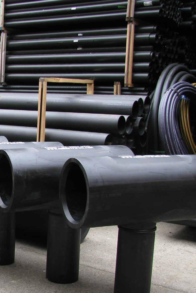
We are a leading manufacturer, fabricator, importer, and supplier of non-corrosive piping systems. We specialise in High Density Polyethylene (HDPE) products for Pressure, Water, Drainage, and Gas applications.
We operate across a wide and diverse range of industry segments and markets, including Mining and Industrial, Water Utilities, Civil and Infrastructure, Coal Seam Gas, Landfill, Agriculture and Irrigation, and Plumbing and Drainage.
In addition to pipe and fittings we also provide a number of value-added services, including custom and specialised fabrication, pipe butt welding, sales and hire of electrofusion and extrusion pipe welding equipment and machinery. We also provide certified in-house electrofusion welder training.
We have a fully equipped and accredited Service Centre to test, repair, and calibrate all major pipe welding machinery brands to OEM specifications and applicable Australian Standards.
YOUR PARTNER IN PIPING SOLUTIONS


12 Loyalty Road, North Rocks, NSW 2151
•
32 Horne Street, Hoppers Crossing, VIC 3029 •
The “Family” code shown at the top of each page refers to the fitting TYPE, e.g. 2014 for an ElectroFusion Coupler. The next four numbers refer to the SIZE, e.g. 0110 for a 110mm fitting, 1163 for a 110mm x 63mm reducer. A 110mm electrofusion coupler is 2014.0110.
All listed pressure ratings are subject to applicable regulations and standards. For further information, please check with your local regulatory authority. All dimensions shown in this catalogue are intended as a guide only and may change without notice. If exact measurements or items not shown in this catalogue are required, please contact our sales team. We are also able to source and supply a wide range of associated products such as valves and non-standard flanges. 19 DATALOGGER DL7


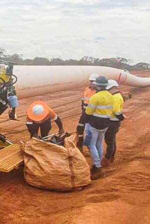
19 SELF-CENTERING STUB END HOLDER 19 IN-DITCH KITS 20 DECOILING TRAILER


LINETAMER 2-4


98
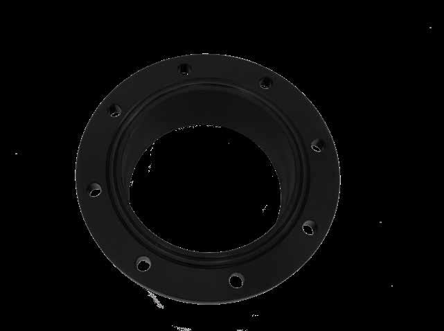
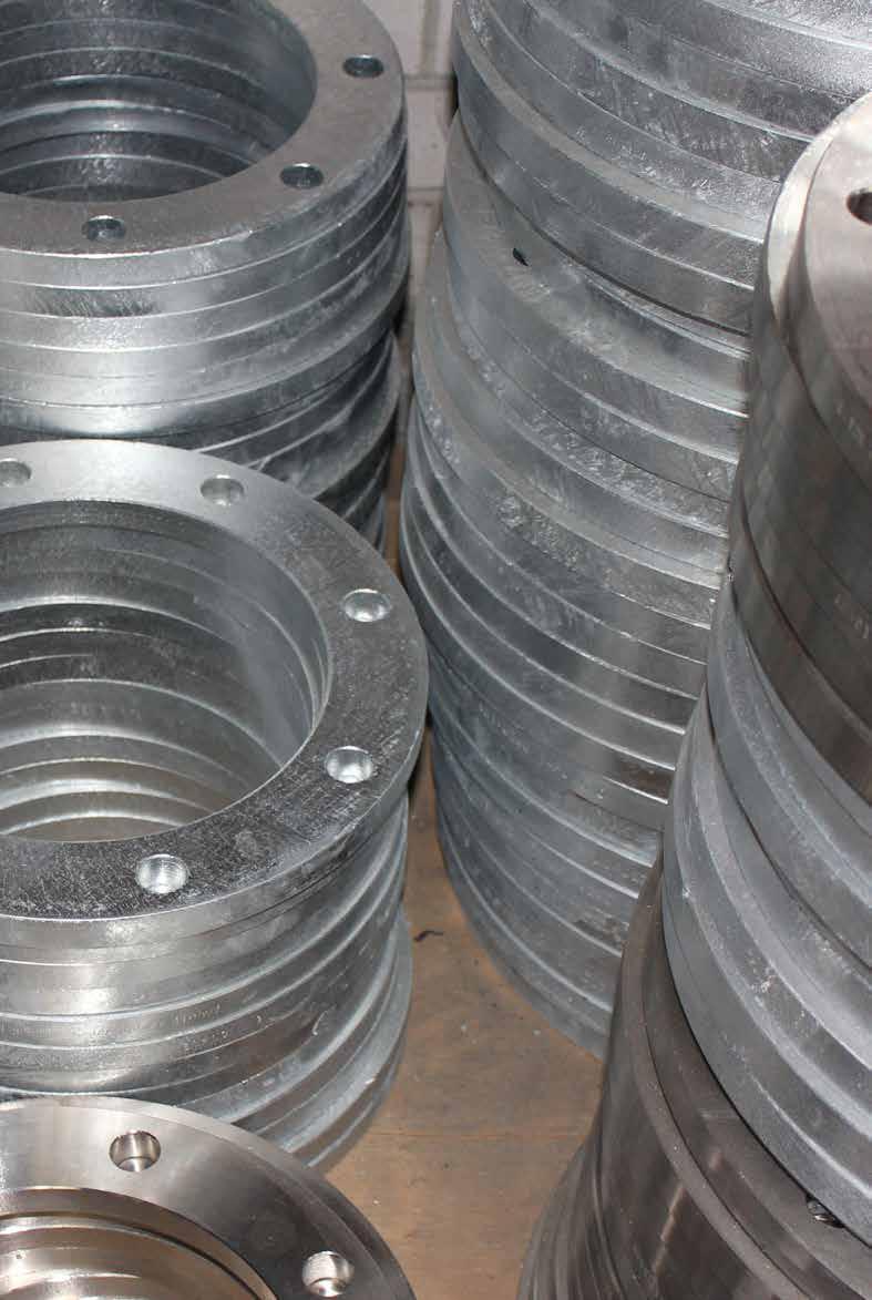
TABLE D BACKING RINGS AND BLIND FLANGES
100
TABLE E BACKING RINGS AND BLIND FLANGES
102
TABLE F BACKING RINGS AND BLIND FLANGES
104
TABLE H BACKING RINGS AND BLIND FLANGES
106
AS4087 PN16 BACKING RINGS AND BLIND FLANGES
108
AS4087 PN21 BACKING RINGS AND BLIND FLANGES
110
ANSI150 BACKING RINGS AND BLIND FLANGES 114
ANSI300 BACKING RINGS AND BLIND FLANGES


907/W907 HDPE-TO-STEEL
116
ANSI150 REDUCED THICKNESS BACKING RINGS AND BLIND FLANGES
118
AS4087 PN35 BACKING RINGS AND BLIND FLANGES 112
ANSI300 REDUCED THICKNESS BACKING RINGS AND BLIND FLANGES 120
DIN PN10 BACKING RINGS AND BLIND FLANGES
DIN PN16 BACKING RINGS AND BLIND FLANGES


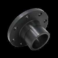
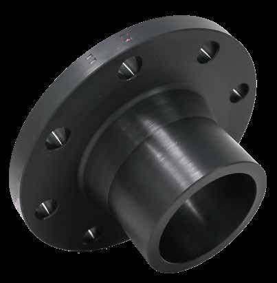
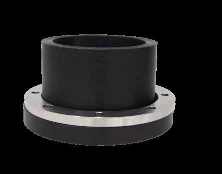
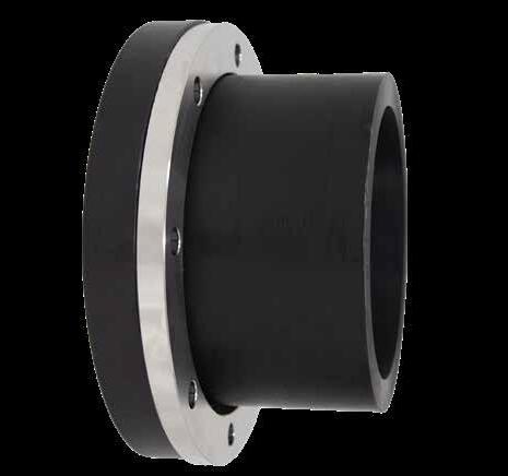
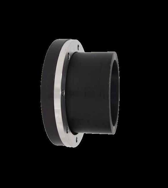
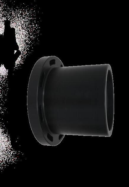
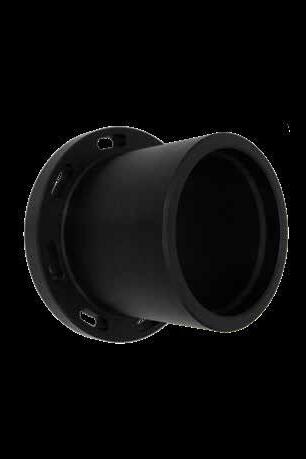
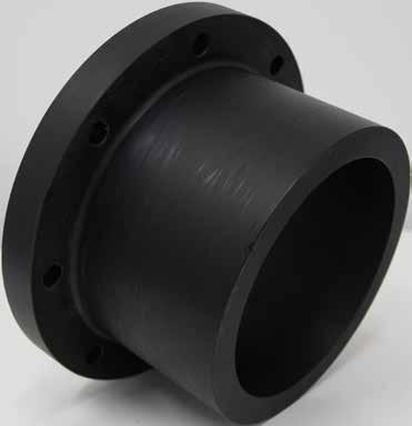
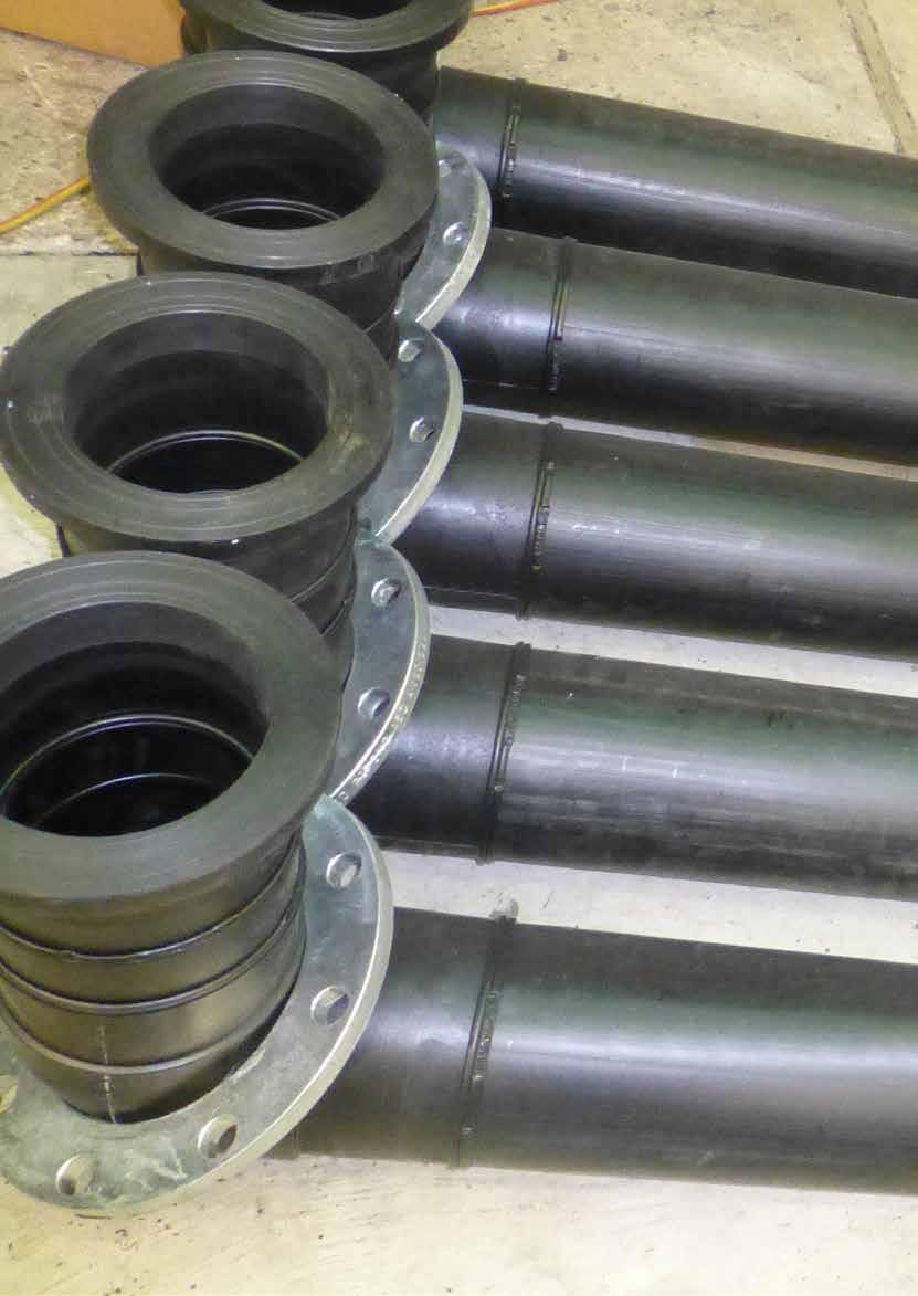
LONG SPIGOT STUB FLANGE


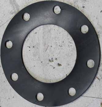
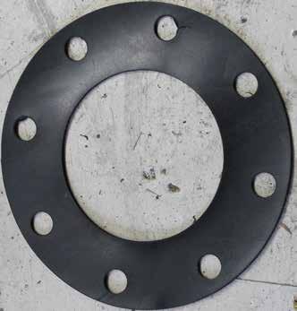
GASKET AND BOLTS


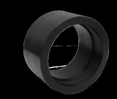
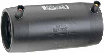
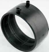
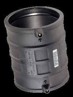
ELECTROFUSION COUPLING


193


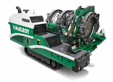
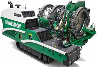
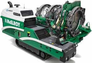
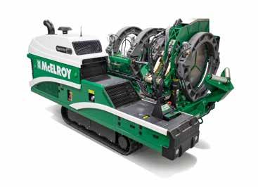
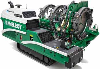
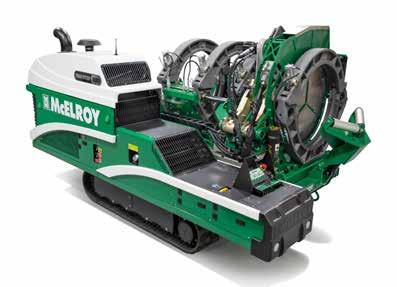
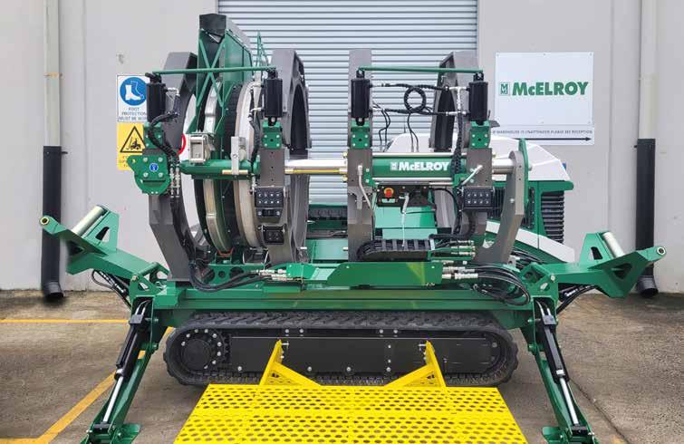
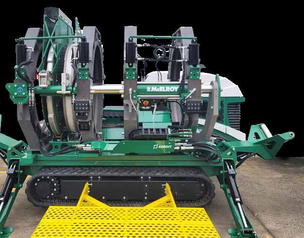
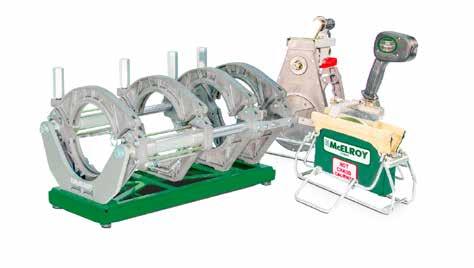
McElroy Service Centre
Adroit has a fully equipped McElroy service and repair centre which is authorised to repair and service McElroy welding equipment and accessories to manufacture’s specifications and Australian standards.
Fusion equipment as dependable as your pipeline
There are plenty of rental fusion machines in the marketplace, but how do you know if your next rental machine is properly maintained and ready to perform?
To secure a premium rental machine, make sure your next rental is from a Certified McElroy Rental equipment fleet.
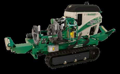

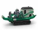
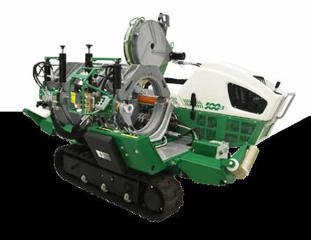
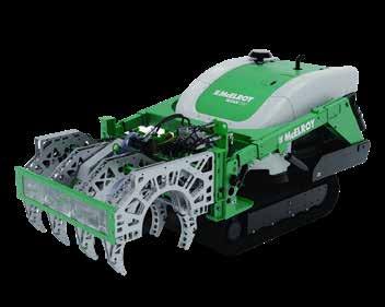
TRACSTAR 500 SERIES 3
160mm-500mm pipe diameter range
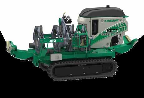
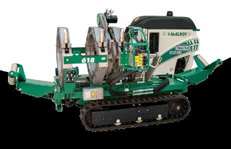
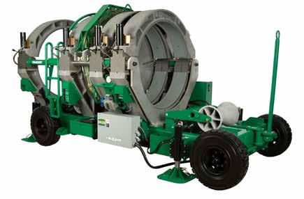
TRACSTAR 630 I SERIES
225-630mm pipe diameter range

TRACSTAR 900 I SERIES
315-900mm pipe diameter range
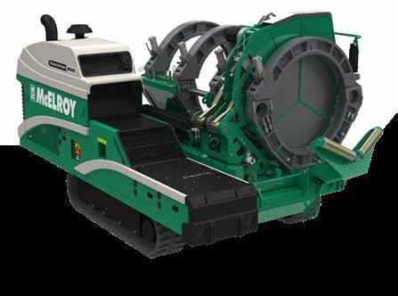
315-900mm pipe diameter range
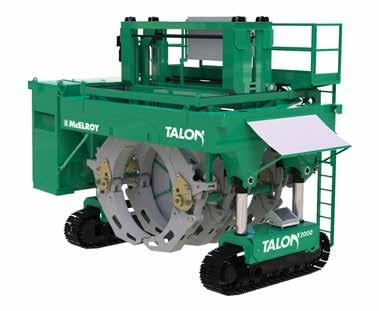
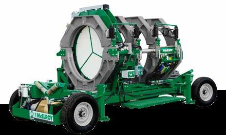
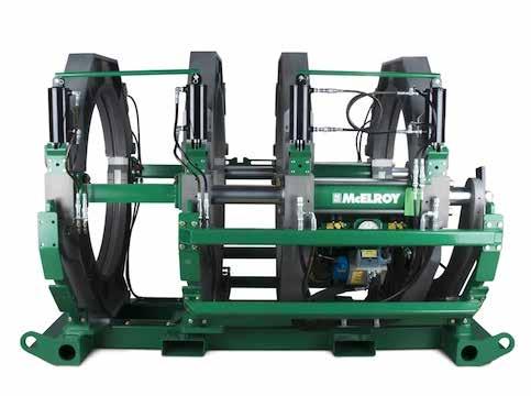
MEGAMC 1648 SERIES 2
450-1200mm pipe diameter range
1600
500-1600mm pipe diameter range
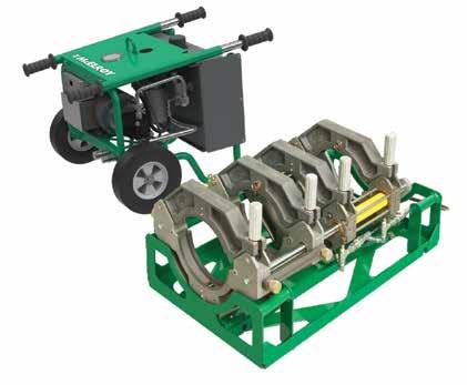
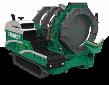
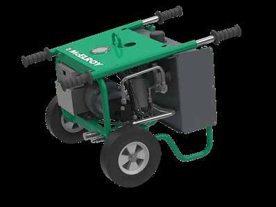
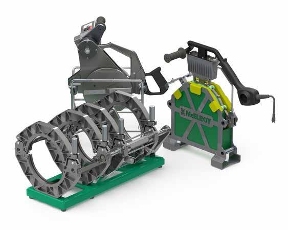
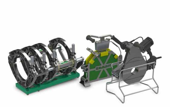
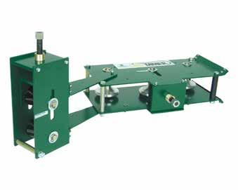
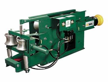
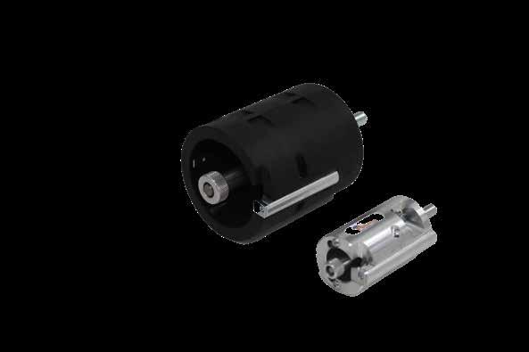
The DynaMc in 2- and 4-jaw configurations. The low cylinder force machines were designed with a small footprint, allowing fusion operators to take the carriage into small working areas. The 28 EP is powered by the EP1500AD Hydraulic Power Unit (HPU), which is a common HPU for a variety of DynaMc EP fusion machines, such as the Sidewall 28 and Compact 28 Vertical. The HPU uses a hydraulic accumulator to maintain fusion pressures and reduce power consumption.
The manual carriage manifold of the DynaMc 28 EP is powerful enough to tackle thick-walled pipe and is paired with a strong electric facer that can be loaded from either side of the carriage. Capable of 1,500 PSI fusion pressures, the DynaMc EP is compatible with the DataLogger
Whether it is one fusion or 100, the DynaMc 28 EP provides the rugged reliabil ity you expect from a McElroy.

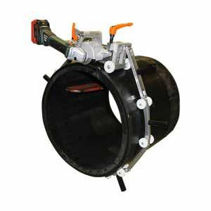
ACROBAT™ 180
63-180mm
ACROBAT™ 250
63-250mm
ACROBAT™ 315
200-315mm

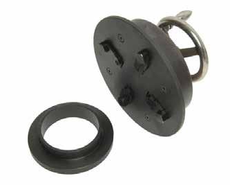
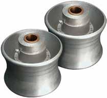
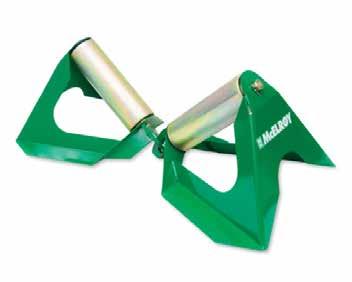
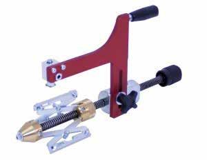
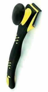
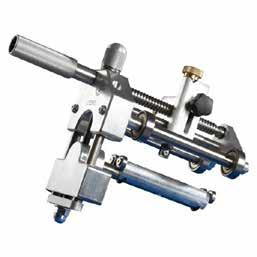
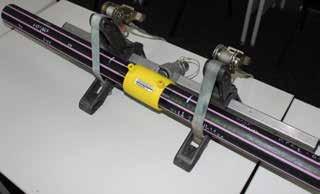
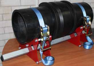
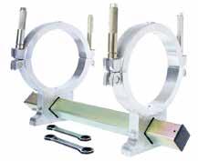
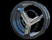
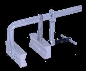
Self-centering stub end holder to hold stub end for butt fusion
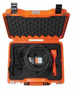
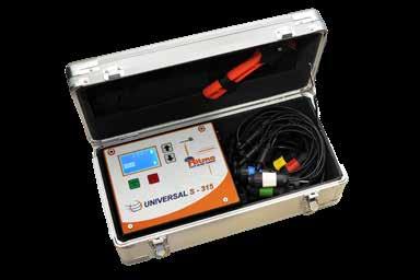
PE WELDING EQUIPMENT PURCHASE AND HIRE
CODE: SPRW.SMART
FEATURES: 3M lead
FITTING SIZE: Up to 180mm (sizes above 100mm require cool down time between welds)
WELDS: Plasson only (competitor allowance with App)
CALIBRATION PERIOD: After 200 hours or 12 months
BARCODE READING CAPABILITY: Yes with App
DATA RECORDING: Yes with App
EARTH PIN: 10A
CODE: SPRW.MONO
FEATURES: 5M lead
FITTING SIZE: Up to 355mm
WELDS: Plasson only (competitor allowance with App)
CALIBRATION PERIOD: After 200 hours or 12 months
BARCODE READING CAPABILITY: Yes with App
DATA RECORDING: Yes with App
EARTH PIN: 15A
CODE: SPRW.POLY
FEATURES: 5M lead
FITTING SIZE: Up to 800mm (sizes above 355mm require cool down time between welds)
WELDS: Any EF fittings
CALIBRATION PERIOD: After 200 hours or 12 months
BARCODE READING CAPABILITY: Yes
DATA RECORDING: Yes with App
EARTH PIN: 15A


FEATURES: 10M lead
FITTING SIZE: Almost all sizes. Some sizes between 800 and 1000mm may require a Manut machine. No cool down required when using Polycontrol Plus V2
WELDS: Plasson only (competitor allowance with App)
CALIBRATION PERIOD: After 200 hours or 12 months
BARCODE READING CAPABILITY: Yes with App
EARTH PIN: 15A
HDPE DRAINAGE E/F WELDER TO SUIT 40-160
CODE: D40.160
INPUT VOLTAGE RANGE: 190-300V
FREQUENCY: 40-70V
MINIMUM OUTPUT: 18A at 240V - one phase
• Must be able to drive inductive loads
• Must have phase cut control
• Mechanically regulated with brushes is the preferred system
• Synchronised generator
MINIMUM: 6.5kVA - Mechanically Controlled
MINIMUM: 7.5kVA - Electronically Controlled

• Graphic display
• Auto recognition of fittings
• Memory with 350 welding reports
• Report in PDF File
A00 Ø 32 ÷ 160mm All A00+ Ø 200 ÷ 315mm Wavin
A01 Ø 200 ÷ 315mm Akatherm, Valsir
A02 Ø 200 ÷ 315mm Geberit
A04 Ø 200 ÷ 315mm Coes
2006020 Spare Blade for Pipe End Peeler 63-200 (0.2mm peeling depth)
2006029 Spare Blade for Pipe End Peeler 90-315/180-400 (0.3mm peeling depth) 2004002 Pipe Cutter Spare Blade for 63mm (Single Hand) 2004003 Pipe Cutter up to 63mm (Tow Hand Use) Spare Blade
2004003
2004002
Pipe Cutter Spare Blade for 63mm (Single Hand)
Pipe Cutter up to 63mm (Tow Hand Use) Spare Blade
Pipe Cutter Spare Blade for 63mm (Single Hand)
2004003 Pipe Cutter up to 63mm (Tow Hand Use) Spare Blade
CODE
DESCRIPTION
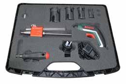
2006035 Drill Powered Pipe end Peeler Incl Bosch Drill and Case
2006058
2006067
2006076
2006059
2006072
2006068
2006060
2006069
2006077
2006061
2006070
2006078
2006062
2006071
Mandrel 32mm SDR11
Mandrel 32mm SDR17
Mandrel 40mm SDR9
Mandrel 40mm SDR11
Mandrel 40mm SDR13.6
Mandrel 40mm SDR17
Mandrel 50mm SDR11
Mandrel 50mm SDR17
Mandrel 63mm SDR7.4
Mandrel 63mm SDR11
Mandrel 63mm SDR17
Mandrel 75mm SDR7.4
Mandrel 75mm SDR11
Mandrel 75mm SDR17
DESCRIPTION
CODE
947777 50/315 HDPE Hand Scraper
947776 50/315 HDPE Hand Scraper blade 2pk

9200.3145

494X.0800
494X.0900

Note:
315-400mm CODE
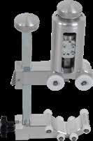
2008019 Hydraulic Jack (315-400)
2008020 Rounding Shell 315mm (Without jack)
2008021 Rounding Shell 355mm (Without jack)
2008022 Rounding Shell 400mm (Without jack)
2008023 Hydraulic Jack (450-630)
2008024 Rounding Shell 450mm (Without jack)
2008025 Rounding Shell 500mm (Without jack)
2008026 Rounding Shell 560mm (Without jack)
2008027 Rounding Shell 630mm (Without jack)
Note: Used to round pipe after squeezing.
2007001
Pipe Clamp 16-63mm
Infinitely variable grip clamps to suit any combination of sizes, 16-63mm
2007002 Pipe Clamp 32-110mm
Infinitely variable grip clamps to suit any combination of sizes, 32-110mm
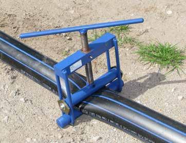
2007011 Pipe Clamp 63-225mm
Infinitely variable grip clamps to suit any combination of sizes, 63-225mm
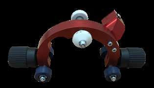
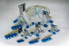
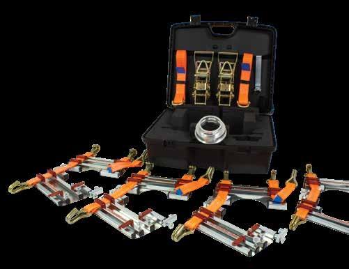
• Adjustable to suit couplers, reducers, 22.5°, 45° and 90° elbows and tees.
• Promotes restraint during the electrofusion process.
• Quick tightening operation, lightweight and easy to use.
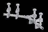
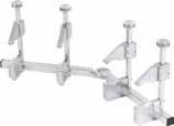
2007005 Pipe Clamp 110-560mm
2007006
4 pipe clamps, 2 base bars, angled adaptor 22.5°, 45°, 90° and 180°
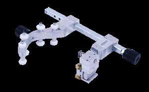
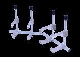
Pipe Clamp 250-800mm
With 2 fixed clamps, 2 clamps required
2007007 Pipe Clamp 250-800mm set
Included in set: 2 complete clamps each with a pulling clamp, a fixed clamp and pulling shoes for couplers. Allows you to pull the coupler over the pipe and the opposite pipe into the coupler to complete the insertion.
2007008 Pipe Support Pipe support to 225mm
DESCRIPTION
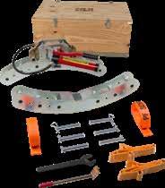
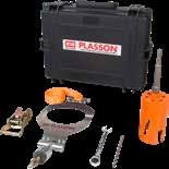
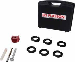
2012001 L Saddle outlet 90-160mm
Includes:
- Splitable plates: 90/110 x 125/160mm
- Pressure Test Spigot Removal Tool
- Rounding Ring 250mm
- Transport Case
2012040 XL Saddle outlet 180-200mm
Includes:
- Splitable Plate: 180/200mm
- Reductions 180mm, 200mm and 225mm for Rounding Ring 250mm
- Transport Case
- Tensioning Tool Kit required 2012020
2012018 XL Saddle outlet 225-250mm
Includes:
- Splitable Plate: 225/250mm
- Rounding Ring 250mm
- Reduction 225mm for Rounding Ring 250mm
- Transport Case
- Tensioning Tool Kit required 2012020
2012029 XXL Saddle outlet 280-315mm
Includes:
- Splitable Plate: 280/315mm
- Pressing Tool 280mm
- Pressing Tool 315mm
- Transport Case
- Tensioning Tool Kit required 2012020
2012049 XXXL Saddle outlet 355-400mm
Includes:
- Splitable Plate: 355/400mm
- Pressing Tool 355mm
- Pressing Tool 400mm
- Transport Case
- Tensioning Tool Kit required 2012020
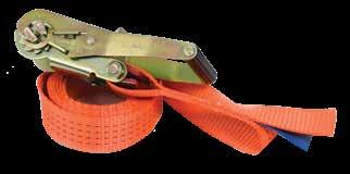
2012020 Straps for clamping all Clamp Kits 180-1200mm
Includes:
- 3 x Straps
- 3 x Ratchets
- Torque wrench
- Torque wrench adapter with fine tooth pitch
- Pressure Test Spigot Removal Tool
- Unlocking tool for ratchets
- Adapter for pressure test pump 1/2"
- Transport Case
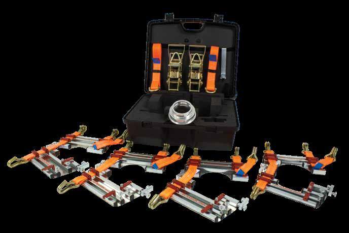
To install a Plasson Large Bore Saddle the following are required:
1. A Clamp Kit to suit the outlet size of the saddle.
2. A Strap Kit for outlet sizes 180-400mm.
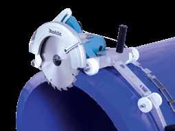
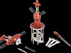
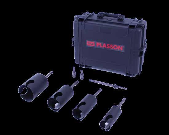
3. A Core Cutter to core the saddle after welding.
4. A Drill/Motor to operate the Core Cutter.
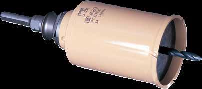
2012002
2012050
2012037
Saddle Outlet
Includes:
1 x 90mm core cutter, Borehole 71mm*
1 x 110mm core cutter, Borehole 87mm*
1 x 125mm core cutter, Borehole 99mm*
1 x 160mm core cutter, Borehole 127mm*
* Equipped with SDS-Max Adaptor
1 x Centre Drill
1 x Drill chuck connector
1 x Connector for SDS-Plus
1 x Transport Case
Saddle outlet 180mm
Core cutter for 180mm outlet, Borehole 143mm
Includes Drill Adaptor and Case
Saddle outlet 200mm
Core Cutter for 200mm outlet, Borehole 159mm
Includes Drill Adaptor and Case
2012044 Saddle outlet 225mm
2012015
2012051
2012028
2012052
2012022
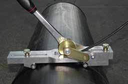
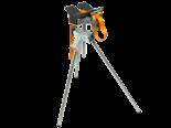
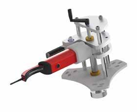
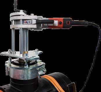
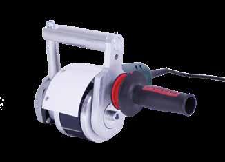
• Saddles with outlets 90-225mm use a hand operated drill.
• Saddles with 250mm outlets can use a hand operated drill.
A safety arm must be used to stabilise the drill.
• Alternatively, the drill can be operated with the motor mounting clamp.
• Saddles 280mm and above use a motor mounting clamp.
• The same motor can be used on all outlets.
Core Cutter for 225mm outlet, Borehole 179mm
Includes Drill Adaptor and Case
Saddle outlet 250mm
Core Cutter for 280mm outlet, Borehole 233mm
Includes Drill Adaptor and Case
Saddle outlet 280mm
Core Cutter for 280mm outlet, Borehole 233mm
Includes Drill Adaptor and Case
Saddle outlet 315mm
Core Cutter for 315mm outlet, Borehole 251mm
Includes Drill Adaptor and Case
Saddle outlet 355mm
Core Cuter for 355mm outlet, Borehole 283mm
Includes Drill Adaptor and Case
Saddle outlet 400mm
Core Cutter for 400mm outlet, Borehole 319mm Includes Drill Adaptor and Case


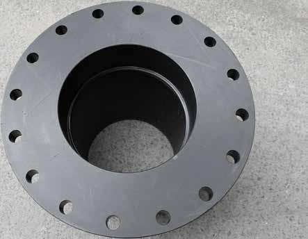
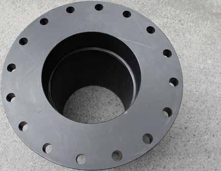
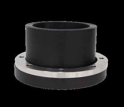
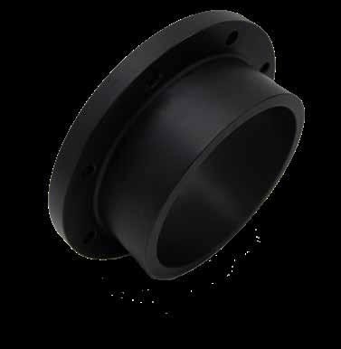
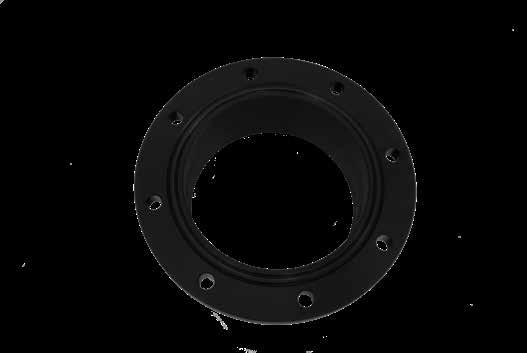
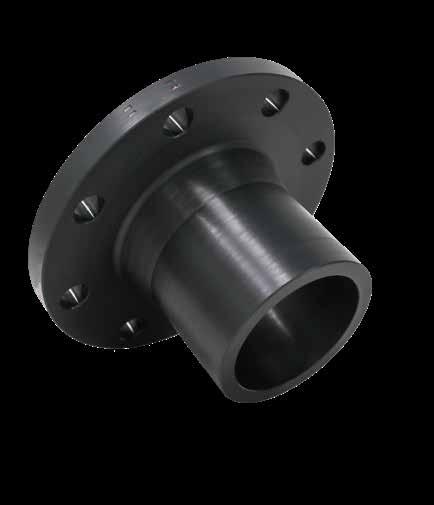
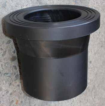
Faced Flanges
Notes for Stub flange: OAL = Overall length. Spgt Lth/SL = Spigot length. HT = Head thickness. OD = Outside diameter.
Note: SDRs and sizes available upon request. All measurements in millimetres. All dimensions are approximate. All dimensions subject to change.
Notes for Stub flange: OAL = Overall length, WT = Weld tail, HT = Head thickness, BR ID = Backing ring internal diameter. Note: SDRs and sizes available upon request. All measurements in millimetres. All dimensions are approximate. All dimensions subject to change.
Notes for Stub flange: OAL = Overall length, WT = Weld tail, HT = Head thickness, BR ID = Backing ring internal diameter.
Note: SDRs and sizes available upon request. All measurements in millimetres. All dimensions are approximate. All dimensions subject to change.
Notes for Stub flange: DP = Drill pattern, OD = Outside diameter, OAL = Overall length, WT = Weld tail, HT = Head thickness, BR ID = Backing ring internal diameter. Note: SDRs and sizes available upon request. All measurements in millimetres. All dimensions are approximate. All dimensions subject to change.

Notes for Stub flange: DP = Drill pattern, OD = Outside diameter, OAL = Overall length, WT = Weld tail, HT = Head thickness, BR ID = Backing ring internal diameter.
Note: SDRs and sizes available upon request. All measurements in millimetres. All dimensions are approximate. All dimensions subject to change.
Notes for Stub flange: OAL = Overall length. Spgt Lth/SL = Spigot length. HT = Head thickness. OD = Outside Diameter. Note: SDRs and sizes available upon request. All measurements in millimetres. All dimensions are approximate. All dimensions subject to change.
Notes for Stub flange: OAL = Overall length. Spgt Lth/SL = Spigot length. HT = Head thickness. OD = Outside Diameter.
Note: SDRs and sizes available upon request. All measurements in millimetres. All dimensions are approximate. All dimensions subject to change.
110-900 4912.0 SDR7.4 to SDR9
110-900 4913.0 SDR9 to SDR11
110-900 4914.0 SDR11 to SDR13.6
110-900 4915.0 SDR13.6 to SDR17
110-900 4916.0 SDR17 to SDR21
110-900 4922.0 SDR7.4 to SDR11
110-900 4923.0 SDR9 to SDR13.6
110-900 4924.0 SDR11 to SDR17
110-900 4925.0 SDR13.6 to SDR21
110-900 4926.0 SDR17 to SDR26
110-900 4932.0 SDR7.4 to SDR13.6
110-900 4933.0 SDR9 to SDR17
110-900 4934.0 SDR11 to SDR21
110-900 4935.0 SDR13.6 to SDR26
110-900 4936.0 SDR17 to SDR33
Note: Other sizes available upon request. All measurements in millimetres. All dimensions are approximate. All dimensions subject to change.
110-900 3912.0 SDR7.4 to SDR9
110-900 3913.0 SDR9 to SDR11
110-900 3914.0 SDR11 to SDR13.6
110-900 3915.0 SDR13.6 to SDR17
110-900 3916.0 SDR17 to SDR21
110-900 3922.0 SDR7.4 to SDR11
110-900 3923.0 SDR9 to SDR13.6
110-900 3924.0 SDR11 to SDR17
110-900 3925.0 SDR13.6 to SDR21
110-900 3926.0 SDR17 to SDR26
110-900 3932.0 SDR7.4 to SDR13.6
110-900 3933.0 SDR9 to SDR17
110-900 3934.0 SDR11 to SDR21
110-900 3935.0 SDR13.6 to SDR26
110-900 3936.0 SDR17 to SDR33
Note: Other sizes available upon request. All measurements in millimetres. All dimensions are


75
75
250
75
4094.2016
4094.3531
4094.4031
in millimetres. All dimensions are approximate. All dimensions subject to change.
Note: All measurements in millimetres. All dimensions are approximate. All dimensions subject to change Custom sizes/SDRs available.
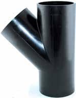
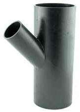
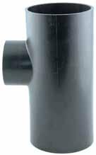
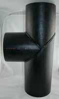
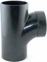
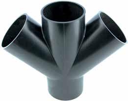
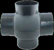
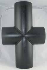
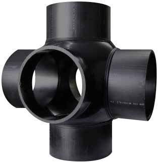
Note: A = Diameter of OD. B = Diameter of branch.
Note: SDRs and sizes available upon request. All measurements in millimetres. All dimensions are approximate. All dimensions subject to change.
Note: Other style’s made to order upon request. All measurements in
To Suit Valve 100NB
To Suit Valve 150NB
To Suit Valve 200NB
To Suit Valve
To Suit Valve 300NB
Note: Alternate Sizes/SDRs available upon request. All measurements in millimetres. All dimensions are approximate. All dimensions subject to change.
To Suit Valve
To Suit Valve 600NB
To Suit Valve 700NB
To Suit Valve
To Suit Valve 900NB
To Suit Valve 1000NB
Note: Alternate Sizes/SDRs available upon request. All measurements in millimetres. All dimensions are approximate. All dimensions subject to change.
Note: Other sizes and combinations available on request.
The Product Code “X” in the table on the left refers to the SDR shown below:
1 = SDR6
2 = SDR7.4
3 = SDR9
4 = SDR11
5 = SDR13.6
6 = SDR17
7 = SDR21
Note: This fitting is suitable for butt welding only but can be extended to suit electrofusion. All measurements in millimetres. All dimensions are approximate. All dimensions subject to change.
Notes for Stub flange: DP = Drill Pattern. OAL = Overall length. Spgt Lth = Spigot length. HT = Head thickness. Notes for Backing ring: B/R ID = Backing ring ID.
Note: Other SDRs available upon request. All measurements in millimetres. All dimensions are approximate. All dimensions subject to change.
Notes for Stub flange: DP = Drill Pattern. OAL = Overall length. Spgt Lth = Spigot length. HT = Head thickness.
Notes for Backing ring: B/R ID = Backing ring ID.
Note: Other SDRs available upon request. All measurements in millimetres. All dimensions are approximate. All dimensions subject to change.

Notes for Stub flange: DP = Drill Pattern. OAL = Overall length. Spgt Lth = Spigot length. HT = Head thickness. Notes for Backing ring: B/R ID = Backing ring ID.
Note: Other SDRs available upon request. All measurements in millimetres. All dimensions are approximate. All dimensions subject to change.
Notes for Stub flange: DP = Drill Pattern. OAL = Overall length. Spgt Lth = Spigot length. HT = Head thickness. Notes for Backing ring: B/R ID = Backing ring ID.
Note: Others SDRs available upon request. All measurements in millimetres. All dimensions are approximate. All dimensions subject to change.
Permits

Notes for Slim flange: DP = Drill Pattern. OAL = Overall length. Spgt Lth = Spigot length. HT = Head thickness.
Notes for Backing ring: B/R ID = Backing ring ID.
Note: Other SDRs available upon request. All measurements in millimetres. All dimensions are approximate. All dimensions subject to change.
AS4087
Notes for Slim flange: DP = Drill Pattern. OAL = Overall length. Spgt Lth = Spigot length. HT = Head thickness.
Notes for Backing ring: B/R ID = Backing ring ID.
Note: Other SDRs available upon request. All measurements in millimetres. All dimensions are approximate. All dimensions subject to change.
450mm x 15in
Notes: OAL = Overall length. Spgt Lth = Spigot length. HT = Head thickness. B/R OD = Backing ring OD. B/R
Notes for Slim flange: DP = Drill Pattern. OAL = Overall length. Spgt Lth = Spigot length. HT = Head thickness. Notes for Backing ring: B/R ID = Backing ring ID.
Note: Other SDRs available upon request. All measurements in millimetres. All dimensions are approximate. All dimensions subject to change.
for
Notes for Backing ring: B/R ID = Backing ring ID. Note: Other SDRs available upon request.
AS2129: TABLE D - PN7/BAR 7/KPA 700/PSI 101
AS2129: TABLE E - PN14/BAR 14/KPA1400/PSI203
AS2129: TABLE H - PN35/BAR 35/KPA 3500/PSI 507
AS2129: TABLE H - PN35/BAR 35/KPA 3500/PSI 507
9911.1250 M12 GAL BOLT AND NUT 50mm
9911.1265 M12 GAL BOLT AND NUT 65mm
9911.1275 M12 GAL BOLT AND NUT 75mm
9911.1610 M16 GAL BOLT AND NUT 100mm
9911.1611 M16 GAL BOLT AND NUT 110mm
9911.1612 M16 GAL BOLT AND NUT 120mm
9911.1613 M16 GAL BOLT AND NUT 130mm
9911.1616 M16 GAL BOLT AND NUT 160mm
9911.1618 M16 GAL BOLT AND NUT 180mm
9911.1650 M16 GAL BOLT AND NUT 50mm
9911.1660 M16 GAL BOLT AND NUT 60mm
9911.1670 M16 GAL BOLT AND NUT 70mm
9911.1675 M16 GAL BOLT AND NUT 75mm
9911.1680 M16 GAL BOLT AND NUT 80mm
9911.1690 M16 GAL BOLT AND NUT 90mm
9911.2010 M20 GAL BOLT AND NUT 100mm
9911.2011 M20 GAL BOLT AND NUT 110mm
9911.2012 M20 GAL BOLT AND NUT 120mm
9911.2013 M20 GAL BOLT AND NUT 130mm
9911.2014 M20 GAL BOLT AND NUT 140mm
9911.2015 M20 GAL BOLT AND NUT 150mm
9911.2016 M20 GAL BOLT AND NUT 160mm
9911.2018 M20 GAL BOLT AND NUT 180mm
9911.2020 M20 GAL BOLT AND NUT 200mm
9911.2040 M20 GAL BOLT AND NUT 40mm
9911.2075 M20 GAL BOLT AND NUT 75mm
9911.2090 M20 GAL BOLT AND NUT 90mm
9911.2408 M24 GAL BOLT AND NUT 80mm
9911.2411 M24 GAL BOLT AND NUT 110mm
9911.2413 M24 GAL BOLT AND NUT 130mm
9911.2414 M24 GAL BOLT AND NUT 140mm
9911.2415 M24 GAL BOLT AND NUT 150mm
9911.2416 M24 GAL BOLT AND NUT 160mm
9911.2418 M24 GAL BOLT AND NUT 180mm
9911.2420 M24 GAL BOLT AND NUT 200mm
9911.2422 M24 GAL BOLT AND NUT 220mm
9911.2424 M24 GAL BOLT AND NUT 240mm
9912.1260 M12 S/S BOLT 50mm
9912.1265 M12 S/S BOLT 65mm
9912.1290 M12 S/S BOLT 90mm
9912.1610 M16 S/S BOLT 100mm
9912.1611 M16 S/S BOLT 110mm
9912.1612 M16 S/S BOLT 120mm
9912.1613 M16 S/S BOLT 130mm
9912.1614 M16 S/S BOLT 140mm
9912.1615 M16 S/S BOLT 150mm
9912.1616 M16 S/S BOLT 160mm
9912.1617 M16 S/S BOLT 170mm
9912.1619 M16 S/S BOLT 190mm
9912.1660 M16 S/S BOLT 60mm
9912.1665 M16 S/S BOLT 65mm
9912.1670 M16 S/S BOLT 70mm
9912.1675 M16 S/S BOLT 75mm
9912.1680 M16 S/S BOLT 80mm
9912.1690 M16 S/S BOLT 90mm
9912.2010 M20 S/S BOLT 100mm
9912.2011 M20 S/S BOLT 110mm
9912.2012 M20 S/S BOLT 120mm
9912.2013 M20 S/S BOLT 130mm
9912.2014 M20 S/S BOLT 140mm
9912.2015 M20 S/S BOLT 150mm
9912.2016 M20 S/S BOLT 160mm
9912.2070 M20 S/S BOLT 70mm
9912.2080 M20 S/S BOLT 80mm
9912.2410 M24 S/S BOLT 100mm
9912.2412 M24 S/S BOLT 120mm
9912.2413 M24 S/S BOLT 130mm
9912.2414 M24 S/S BOLT 140mm
9912.2415 M24 S/S BOLT 150mm
9912.2416 M24 S/S BOLT 160mm
9921.0012 M12 GAL NUT
9921.0016 M16 GAL NUT
9921.0020 M20 GAL NUT
9921.0024 M24 GAL NUT
9931.0012 M12 GAL WASHER
9931.0016 M16 GAL WASHER
9931.0020 M20 GAL
Note: Other sizes available upon request. SS316 also available upon request.

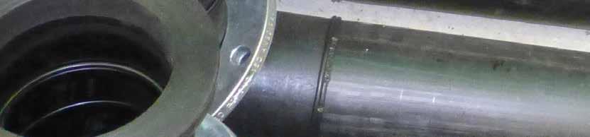
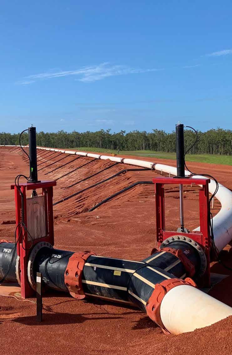
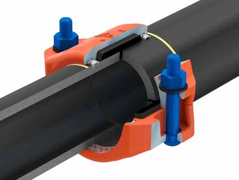
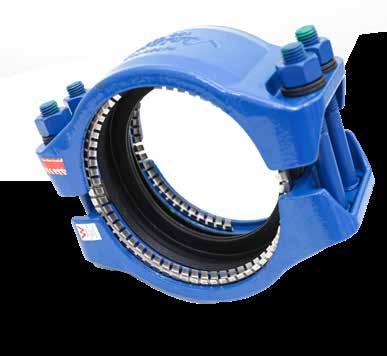
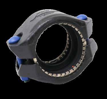
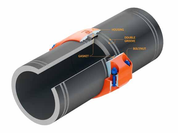
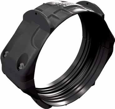
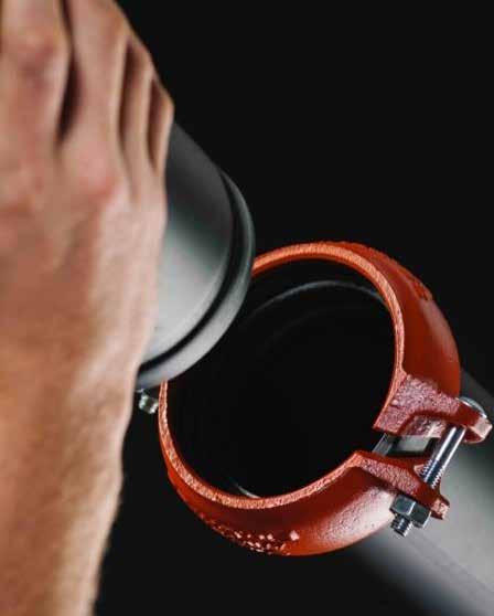
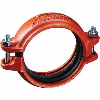
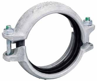
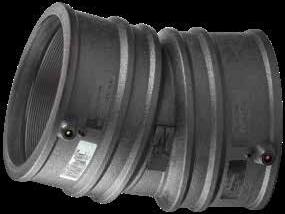
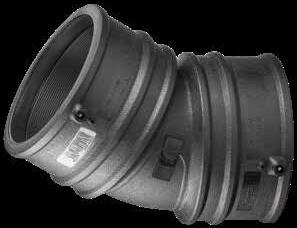
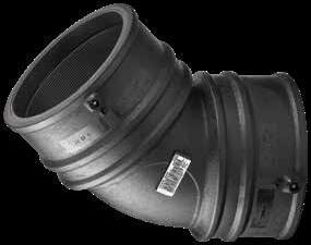
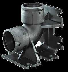
THE INDUSTRY’S FIRST-EVER INSTALLATION-READY™ PLAIN END AND GROOVED TECHNOLOGY FOR MECHANICALLY JOINING HIGH-DENSITY POLYETHYLENE (HDPE).
Note: Unthreaded through holes for appropriately sized lifting eyes or hooks. Metric bolts/nuts standard, with the exception of North American, South American, and Australian shipments, where imperial sizes are standard.
Note: Pressure rating meets or exceeds the performance capabilities of the pipe.
Note: Pressure rating meets or exceeds the performance capabilities of the pipe.
Note: Unthreaded through holes for appropriately sized lifting eyes or hooks. Metric bolts/nuts standard, with the exception of North American, South American, and Australian shipments, where imperial sizes are standard.

Note: The allowable pipe end separation dimension is for system layout purposes only.
Metric bolt/nuts standard, with the exception of North American, South America and Australian shipments, where imperial sizes are standard.
Actual Outside Diameter shown is the average of the minimum OD and the maximum of the given Nominal Pipe Diameter as designated in ISO 4427-2.
Note: For sizes above 900mm, Contact for details. Pressure rating meets or exceeds the performance capabilities of the pipe. Standard Victaulic coupling assembly procedure used for installation.

Note: For sizes above 900mm, Contact for details. Pressure rating meets or exceeds the performance capabilities of
Standard Victaulic coupling assembly procedure used for installation.
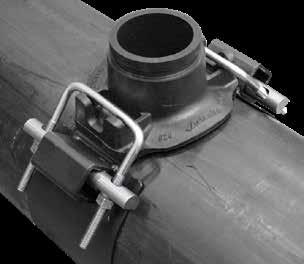
Note: Prepare pipe in accordance with the dimensions above.
For HDPE pipe, Style 926 Hole Saw is recommended. A Milwaukee ½” Hole-Hawg Drill 300/1200 RPM or similar hole saw power drive is recommended for proper hole penetration. For steel and ductile iron pipe, use hole saws designed for metallic pipe.
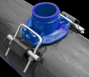
Note: 4”-114.3mm outlets available for 250-800mm mainline pipe diameters. 6”-168.3mm outlets available for 400-1200mm mainline pipe diameters.
Note: Pressure rating meets or exceeds the performance capabilities of the pipe.
Note: 4”-114.3mm outlets available for 250-800mm mainline pipe diameters. 6”-168.3mm outlets available for 400-1200mm mainline pipe diameters.
2 Working Pressure and End Load are total, from all internal and external loads, based on standard weight (ANSI) steel pipe,
specifications. See the Listings/Approvals section of this publication for ratings on other pipes.
3 The allowable pipe separation dimension shown is for system layout purposes only. Style 009N couplings are considered rigid connections and will not accommodate
contraction of the piping system.
Note: When assembling Style 009N or Style 109 couplings onto end caps, take additional care to make certain the end cap is fully seated against the gasket end stop. For Style 009N or Style 109 couplings, use FireLock No. 006 end caps containing the “EZ” marking on the inside face or No. 60 end caps containing the “QV EZ” marking on the inside face. Non-Victaulic end cap products shall not be used with Style 009N or Style 109 couplings. IMPORTANT: Gaskets intended for the Style 009 or Style 009V couplings cannot be used with the Style 009N or Style 109 coupling. There is no interchanging of gaskets or housings between coupling styles.
Use Of FlushSeal Gaskets For Dry Pipe Systems Style 009N or Style 109 couplings are supplied with Grade “E” Type A gaskets. These gaskets include an integral pipe stop, that once installed provides the similar benefits as a FlushSeal gasket for dry pipe systems. It should be noted that standard Victaulic FlushSeal gaskets cannot be used with the Style 009N or Style 109 couplings. The Allowable Pipe End Separation dimension shown is for system layout purposes only. Style 009N or Style 109 Installation-Ready rigid couplings are considered rigid connections and will not accommodate expansion/ contraction or angular movement of the piping system. Contact Victaulic for torsional resistance information.
1.25/DN32
1.5/DN40 1.900/48.3 9015.0483
Note: Pressures up to 365psi | 2517kPa | 25 bar.
11/4/DN32 1.660/42.4 9016.0424 11/2/DN40 1.900/48.3 9016.0483
2/DN50 2.375/60.3 9016.0603 21/2 2.875/73.0 9016.0730 DN65 3.000/76.1 9016.0761
3/DN80 3.500/88.9 9016.0889
Note: Pressures up to 365psi | 2517kPa | 25 bar.
Note: SDR9 available 90mm-800mm. SDR7.4 available 90mm-710mm. Other SDRs available upon request. All measurements in millimetres. All dimensions are approximate. All dimensions subject to change.
Note: All measurements in millimetres. All dimensions are approximate. All dimensions subject to change.
Note: All measurements in millimetres. All dimensions are approximate. All dimensions subject to change. 450 Lightfit Coupler is 42V Fitting- D32:H34 40V 500-800 Lightfit Couplers have dual weld zones Max SDR26 for pipes 63-90mm. Max SDR33 for pipes 110-800mm except 400,560 Max SDR41. Super Light fit Coupler available upon request sizes 500-1000mm.
Note: All measurements in millimetres. All dimensions are approximate. All dimensions subject to change.
Note: All measurements in millimetres. All dimensions are approximate. All dimensions subject to change.

Note: All measurements in millimetres. All dimensions are approximate. All dimensions subject to change.
Note: All measurements in millimetres. All dimensions are approximate. All dimensions subject to change.
Note:
Note: All measurements in millimetres. All dimensions are approximate. All dimensions subject to change. Will require coupling on branch. * Enlarged offtake Tee.

Note: All measurements in millimetres. All dimensions are approximate. All dimensions subject to change Will require coupling on branch.

Note: Other sizes available upon request. Strap clamp needed to install large bore saddles. Will require coupling on branch.
Note: * Cut hole after welding and cooling completed. * 110mm to 250mm with 2” outlet come with Strap underpart. * Saddle size 250-800mm required specialised. * Installation strap clamp.
2234.4512.15
2234.4512.20
2234.4512.25
x 3/4"
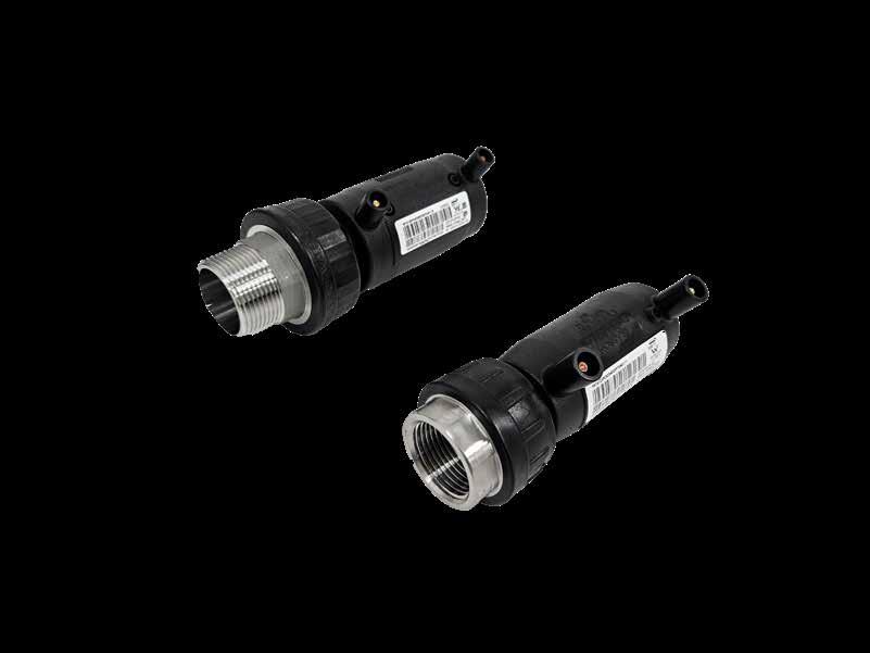
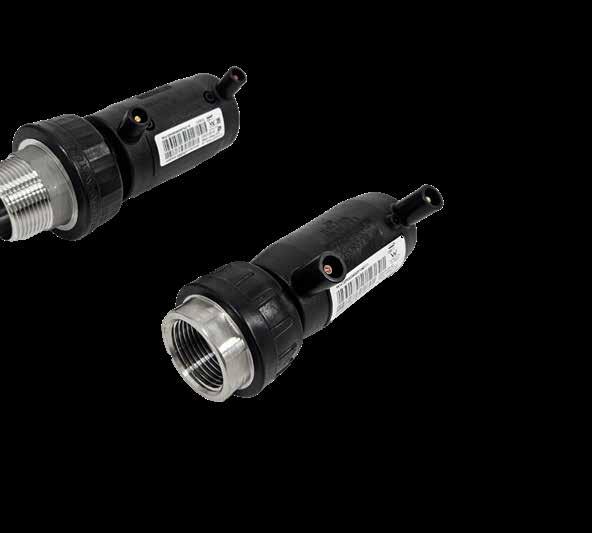
Note: Specialised installation tooling with an option strap or bolt to hold sensor adaptor in place on the pipe required during welding. A barcode reading EF machine is required to install the Plasson sensor adaptor.
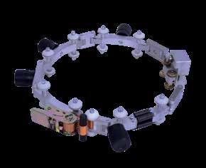
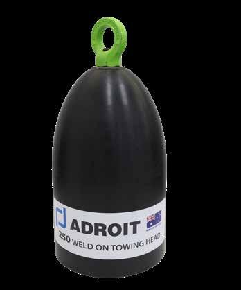
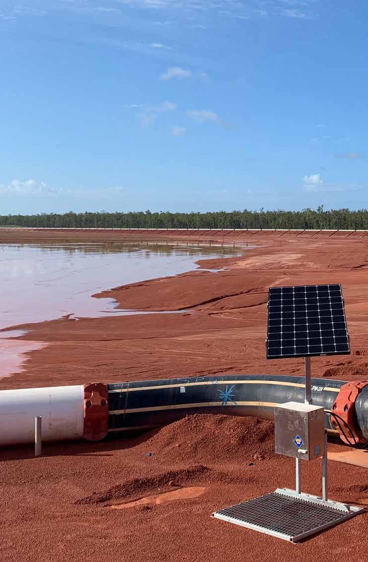
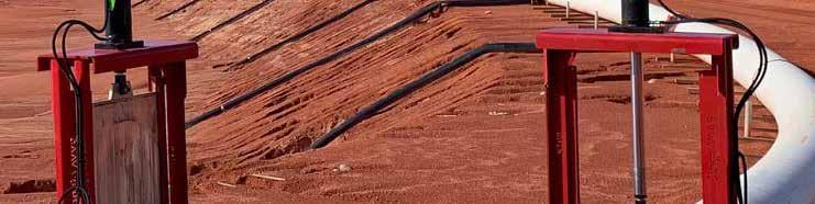
Note: Fits any PE pipe in the size range of 160-1600mm Made from virgin PE100 resin. Can be welded by any standard EF control box with barcode reading or manual input. Design and tested to support 31,000N (3,100kg) of axial force. Use multiple units to achieve required force.
Note: All measurements in millimetres. All dimensions are approximate. All dimensions subject to change. * Will require coupling on branch. * Will require Hex Key, see page 41 Tooling. * Other sizes avalible.
Note: Other sizes available upon request All measurements in millimetres. All dimensions are approximate. All dimensions subject to change.
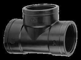
Note: Other sizes and male and female threads available on request. All measurements in millimetres. All dimensions are approximate. All dimensions subject to change.
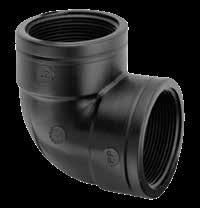
Note: 45 degree and 90 degree available upon request. All measurements in millimetres. All dimensions are approximate. All dimensions subject to change Extra sizes possible for threaded adaptors.
Note: 45 degree and 90 degree available upon request. All measurements in millimetres. All dimensions are approximate. All dimensions subject to change Extra sizes possible for threaded adaptors.
Note: All measurements in millimetres. All dimensions are approximate. All dimensions subject to change. Extra sizes possible for threaded adaptors.
Note: All measurements in millimetres. All dimensions are approximate. All dimensions subject to change. Extra sizes possible for threaded adaptors.
Description
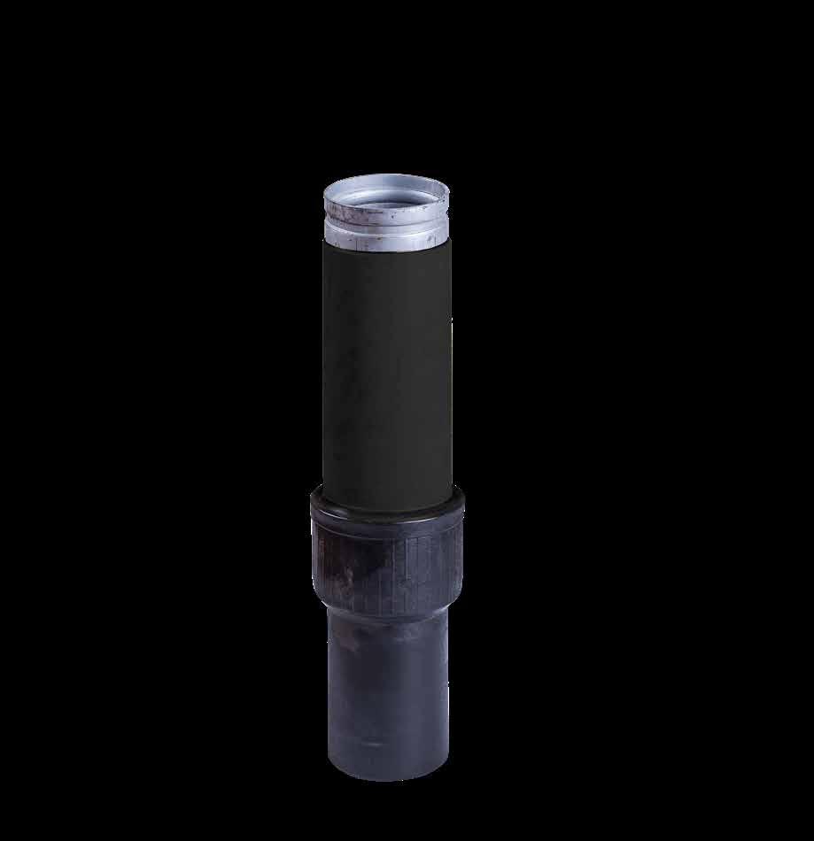
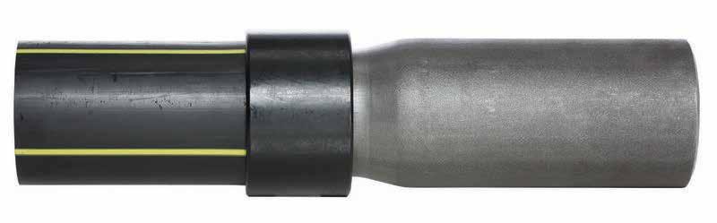
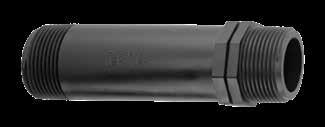
DN32-DN25 PE100-Steel Transition Fitting
DN40-DN32 PE100-Steel Transition Fitting
DN50-DN40 PE100-Steel Transition Fitting
DN63-DN50 PE100-Steel Transition Fitting
DN110-DN100 PE100-Steel Transition Fitting
DN125-DN100 PE100-Steel Transition Fitting
Note: Stainless steel and other materials available upon request. Will require coupling reference page 145.

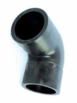
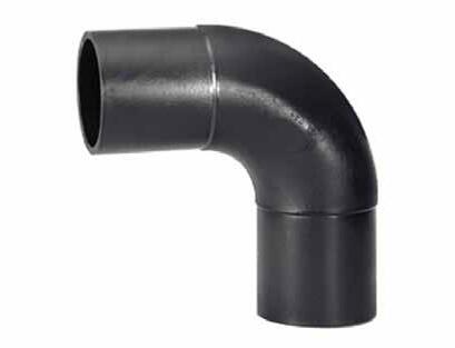
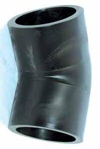
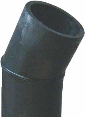
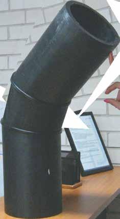
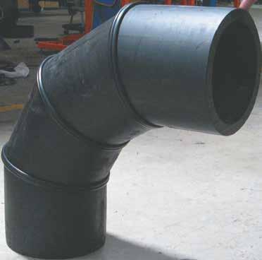
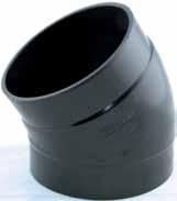
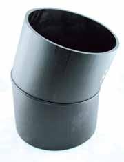
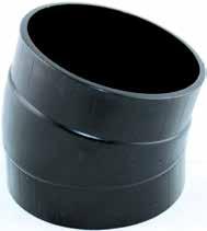
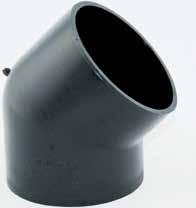
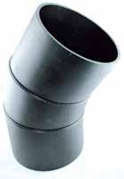
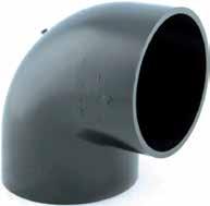
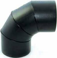
Note: Bends of any required angle can be made to order. All measurements in millimetres. All dimensions are approximate. All dimensions subject to change. Other SDRs available upon request.
Note: Bends of any required angle can be made to order. All measurements in millimetres. All dimensions are approximate. All dimensions subject to change. Other SDRs available upon request.
Note: Bends of any required angle can be made to order. All measurements in millimetres. All dimensions are approximate. All dimensions subject to change. Other SDRs available upon request.
Note: Bends of any required angle can be made to order. All measurements in millimetres. All dimensions are approximate. All dimensions subject to change. Other SDRs available upon request.
Note: Bends of any required angle can be made to order. All measurements in millimetres. All dimensions are approximate. All dimensions subject to change. Other SDRs available upon request.
Note: Bends of any required angle can be made to order. All measurements in millimetres. All dimensions are approximate. All dimensions subject to change. Other SDRs available upon request.
Note: Bends of any required angle can be made to order. All measurements in millimetres. All dimensions are approximate. All dimensions subject to change. Other SDRs available upon request.

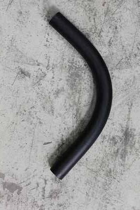
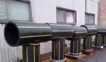
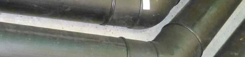
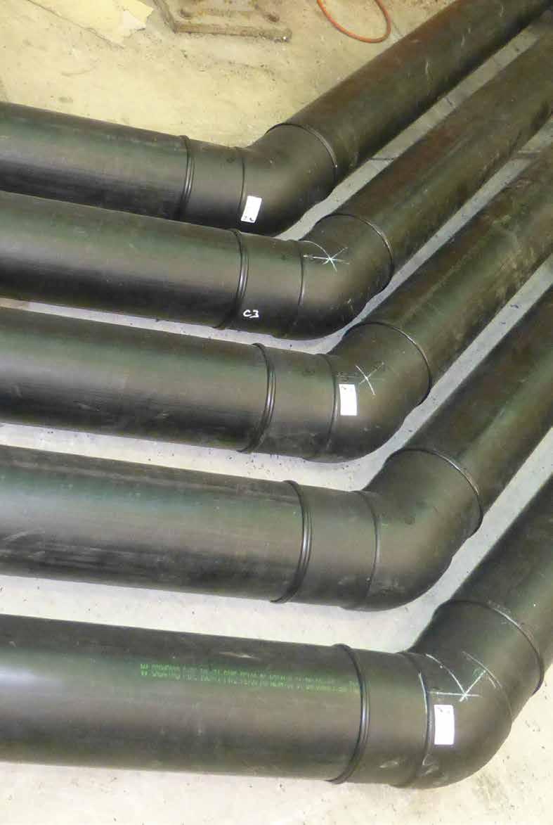
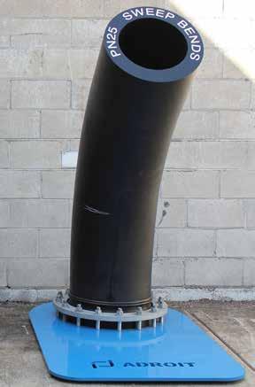
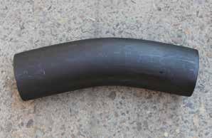
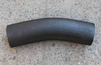
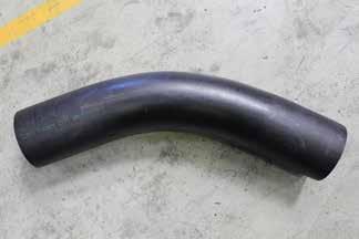
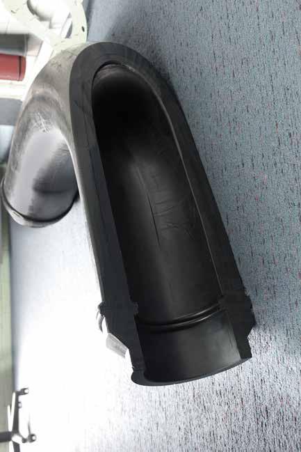
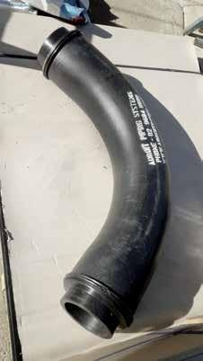
hard wearing legendary multi-wall sweep bend
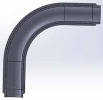
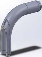
Advantages
More than double the life of a standard sweep bend
Reduced maintenance costs and downtime
Available in any angle up to 90°
Australian made to suit Australian conditions
Applications
Mine wash plants
Mine pipelines
Quarries
Sand mining and dredging
High wear and abrasive applications
Patent no. 2015905170
FITTINGS FOR PRESSURE APPLICATIONS
Note: SDR9 available 90mm-800mm. SDR7.4 available 90mm-710mm. Other SDRs available upon request Other sizes available upon request. All measurements in millimetres. All dimensions are approximate. All dimensions subject to change.
Note: All measurements in millimetres. All dimensions are approximate. All dimensions subject to change. Other SDRs available upon request.
Note:
Note:
Note: All measurements in millimetres. All dimensions are approximate. All dimensions subject to change.
Note: All measurements in millimetres. All dimensions are approximate.

Note: All measurements in millimetres. All dimensions are approximate. All dimensions subject to change.
Note: All measurements in millimetres. All dimensions are approximate. All dimensions subject to change.


Note: Other SDRs available upon request. All measurements in millimetres. All dimensions are approximate. Fittings derate as per POP0060. All dimensions subject to change.
Note: Other SDRs available upon request. All measurements in millimetres. All dimensions are approximate. Fittings derate as per POP006. All dimensions subject to change.
Note: Other SDRs available upon request. All measurements in millimetres. All dimensions are approximate. Fittings derate as per POP006. All dimensions subject to change.
Note: Other SDRs available upon request. All measurements in millimetres. All dimensions are approximate. Fittings derate as per POP006. All dimensions subject to change.


Note: Bends of any required angle can be made to order. All measurements in millimetres. All dimensions are approximate. All dimensions subject to change. Other SDRs available upon request. Fittings derate as per POP006.0.
Note: Bends of any required angle can be made to order. All measurements in millimetres. All dimensions are approximate. All dimensions subject to change. Other SDRs available upon request. Fittings derate as per POP006.
Note: Bends of any required angle can be made to order. All measurements in millimetres. All dimensions are approximate. All dimensions subject to change. Other SDRs available upon request. Fittings derate as per POP006.

Note: Bends of any required angle can be made to order. All measurements in millimetres. All dimensions are approximate. All dimensions subject to change. Other SDRs available upon request. Fittings derate as per POP006.
Note: All measurements in millimetres. All dimensions are approximate. All dimensions subject to change.
Note:
Note: All measurements in millimetres. All dimensions are approximate. All dimensions subject to change.
Note: All measurements in millimetres. All dimensions are approximate. All dimensions subject to change.

Note: All measurements in millimetres. All dimensions are approximate. All dimensions subject to change.
Note: All measurements in millimetres. All dimensions are approximate. All dimensions subject to change.
6163.2590R 6164.2590R
6163.2511R
6163.2512R 6164.2512R 6166.2512R
6163.2890R
6163.2811R 6164.2811R
6163.3190R 6164.3190R 6166.3190R
6163.3116R 6164.3116R
6163.3590R
Note: All measurements in millimetres. All dimensions are approximate. All dimensions subject to change.
PE100 SDR9 SDR11 SDR17
6163.4516R
6163.4518R
6163.5011R
Note: All measurements in millimetres. All dimensions are approximate. All dimensions subject to change.
6163.8028R 6164.8028R
6163.8031R 6164.8031R
6163.8035R 6164.8035R 6166.8035R
6163.8040R
6163.8045R
6163.9012R 6164.9012R 6166.9012R
6163.9016R 6164.9016R 6166.9016R
6163.9018R 6164.9018R 6166.9018R
6163.9020R 6164.9020R 6166.9020R
6163.9025R 6164.9025R 6166.9025R
6163.9028R 6164.9028R 6166.9028R
6163.9031R 6164.9031R 6166.9031R
6163.9035R 6164.9035R 6166.9035R
6163.9040R 6164.9040R 6166.9040R
6163.9045R 6164.9045R 6166.9045R
6163.9050R 6164.9050R 6166.9050R
6163.1090R 6164.1090R 6166.1090R
6163.1011R 6164.1011R
6163.1025R
6163.1035R
6163.1222R
Note: All measurements in millimetres. All dimensions are approximate. All dimensions subject to change.
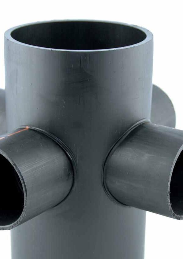
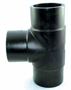
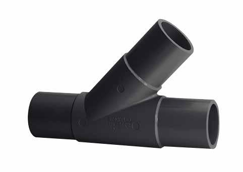
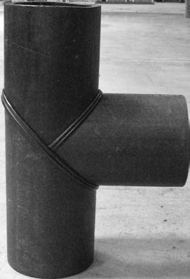
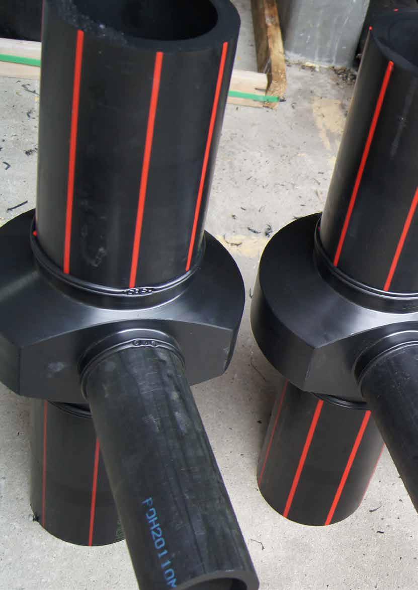
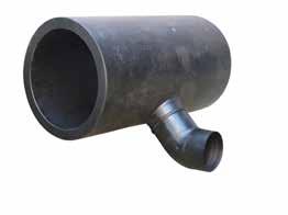
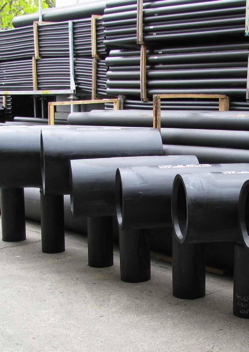
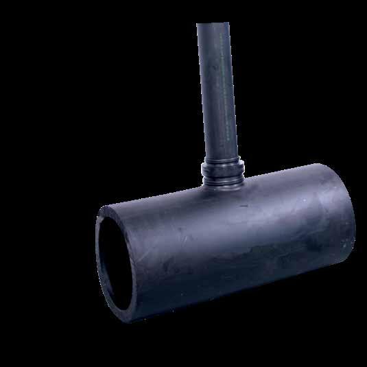
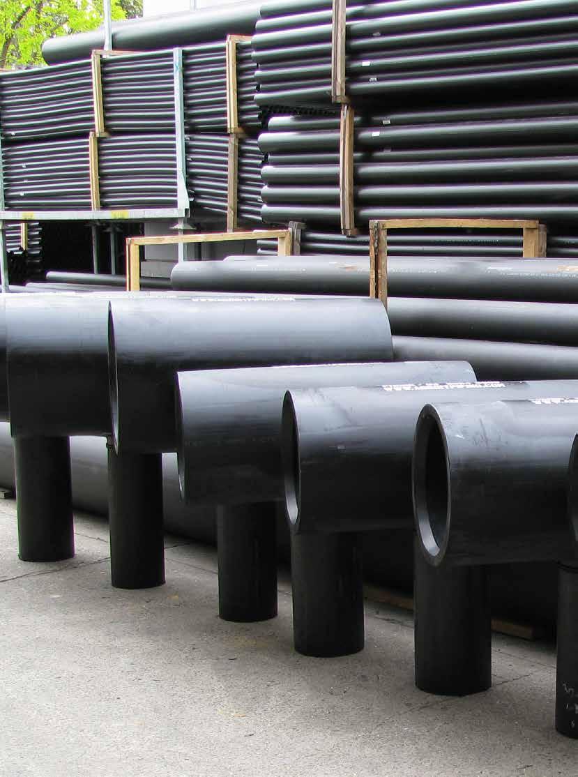
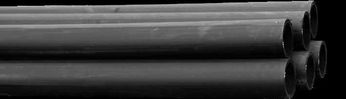
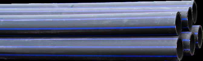
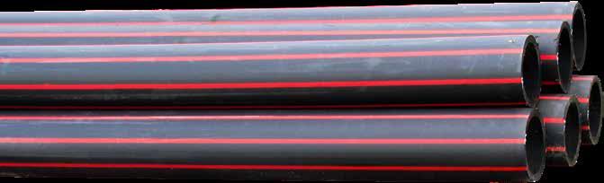
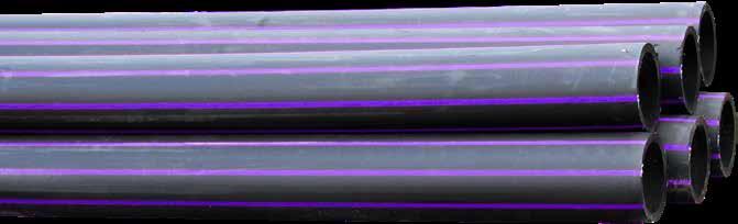
Adroit Piping Systems has a comprehensive range of fully rated forge moulded reducing tees


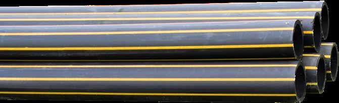
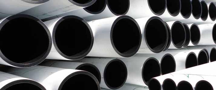
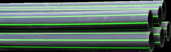
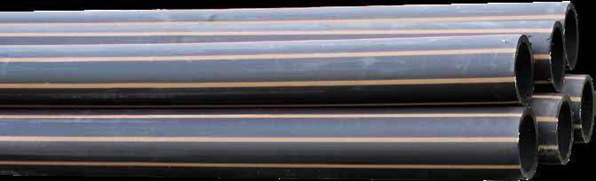
• Black
• Red Line
• Blue Line
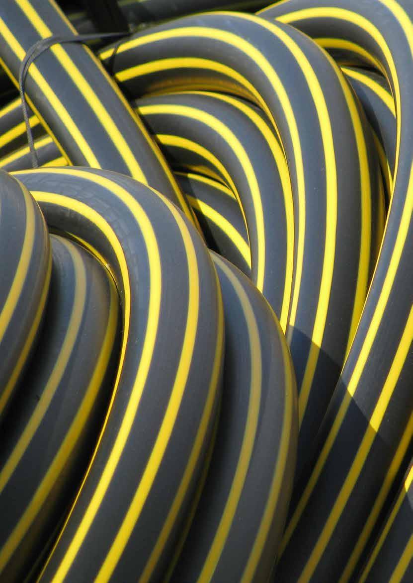
• Yellow Line
• Lilac Line
• Co – Ex
• PN4 up to PN25
• Coils and Lengths
• Green Line
• Beige (Cream) Line


Note: Other sizes, lengths, SDRs and Colours available upon request.
Note: Other sizes, lengths, SDRs and Colours available upon request.
Note: Other sizes, lengths, SDRs and Colours available upon request.
Note: Other sizes, lengths, SDRs and Colours available upon request.
Note:


HB360/145
HB380/170
HB430/145
HB910/450
HB1020/560
HB1130/860
• Colours: PE100 black.
• Standard length: 3000mm.
• Cut lengths available in any required length.
• In case of order, please indicate the finished dimensions of your construction piece.
• Tolerance on request. Plus 10%. Minus 0%.

• Colours: PE100 black.
• For OD 200 in pipe quality PE100 or PP-R.
• Supply lengths: OD 500mm: 2000mm; > OD 500mm: 1000mm.
• Cut in other lengths possible.
• When ordering please indicate the final dimensions of construction piece.
• Tolerance on request. Plus 10%. Minus 0%.
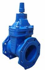
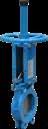
• Suitable for potable water (blue), recycled water (lilac), and waste water.
• Ductile iron, epoxy resin coated body and wedge.
• Rubber bended ductile gate.
• EPDM O-ring and seal bushing and a stainless steel 431 steam. Other types of seats available upon request.
• Maximum working temperature 40°C.
• Allowable operating pressure of 1600kPa.
• Design compliant with AS/NZS2638.2 (80-600mm).
• Flanges compliant with AS4087 and AS2129.
• Maximum test pressure: 2400kPa.
• Epoxy resin coating is fully compliant with AS/NZS4158.
• Valves are distinguished by white cap for anticlockwise and red cap for clockwise closing.
500

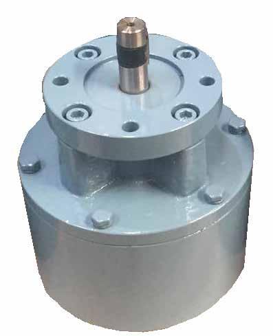
• Working pressure: 300psi.
• Working pressure: -10 to 80°C.
• Ductile Iron body and cover.
• Coated in accordance with standard.
• Forged stem provides stronger stem operation.
• O-Ring stem seals are designed to prevent stem leakage and allow for replacement.
Application:
• The OS&Y Rising Spindle Gate Valves are for use in fire application. The valves are available in Flanged Table E.
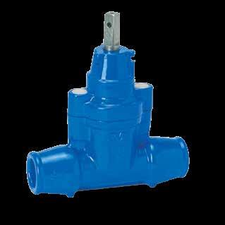
• Tensile resistant sockets to suit PE pipe.
• Thermally bonded epoxy resin coated ductile iron.
• DZR brass wedge vulcanised with EPDM rubber.
• Suited for 25-63mm service lines.
Use:
• For water, sewage and neutral liquid applications.
• Valve designed for use up to 70°C.
• Where applicable; for AS4020 compliance, max temp = 40°C.
Tests:
• Hydraulic test to DIN 3230 part 4:
• Seat: PN.
• Body: 1.5 x PN.
• Operating torque test.
Approvals:
• Va 1.51/dk 5958.
Note: Always observe pipe material recommended operating temperatures PE-pipe material to max. 20°C.
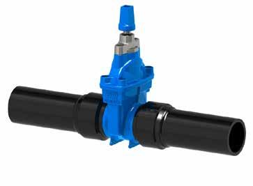
Use:
Use:
• For water, sewage and neutral.
• Valve designed for use up to 70°C.
• Where applicable; for AS4020 compliance, max temp = 40°C.
• PE-pipe material to max. 20°C.
Note: Always observe pipe material recommended operating temperatures.
• For water, sewage and neutral liquid applications
• Valve designed for use up to 70oC
• Where applicable; for AS 4020 compliance, max temp = 40oC
• PE-pipe material to max. 20oC Note: Always observe pipe material recommended operating temperatures tests:
• Valve Hydraulic test to AS 2638.2: - Seat: 17.6 bar - Body: 24 bar - Operating torque test Material design and testing to AS
• Handwheel (refer to series 36/28) • ISO flange for gearbox/actuation (refer to series 36 /22)
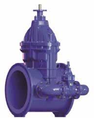
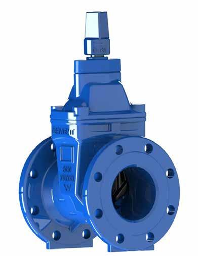
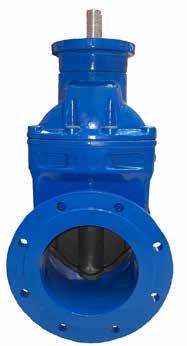
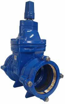
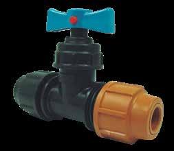
Resilient Seated Gripper Valves for PE, made in conjunction with AFC, are manufactured to AS/NZS 2638.2. The Gate Valves are light weight and applicable for water and waste water applications. Valves are available in both Anticlockwise and Clockwise configuration. Valves are supplied with Key Cap as standard, Hand Wheel is optional.
Features:
• Ductile Iron body and bonnet to AS1831.
• Wedge is Ductile Iron AS1831, fully encapsulated (Vulcanized) EPDM Rubber to AS1646 and AS681.1.
• Forged Stem: 431 Stainless Steel to ASTM A276, providing excellent corrosion and strength, reducing moving parts.
• Bolts are all 316 Stainless Steel to ASTM A276, hot melt encapsulated for superior corrosion resistance in harsh environments.
• Fusion Bonded Epoxy coated to AS/NZS 4158 provides the valve excellent corrosion protection.
• The wedge is designed with abrasion resistant nylon guides which reduce the required opening and closing torque through smooth operation.
Applications:
Gate Valves are for use in potable water, waste water, fire, irrigation, water circulation and heating and cooling applications and are suitable for both above and below ground installation.
Technical Information:
Size range: DN80-DN300.
Allowable Operating Pressure: 1600kPa; 1.6Mpa.
Maximum Test Pressure: 2400kPa, 2.4Mpa.
Maximum Temperature: 40°C.
Certification: SAI Global.
Standards Mark: SMK25890. WSAA: PA1511.
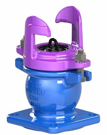
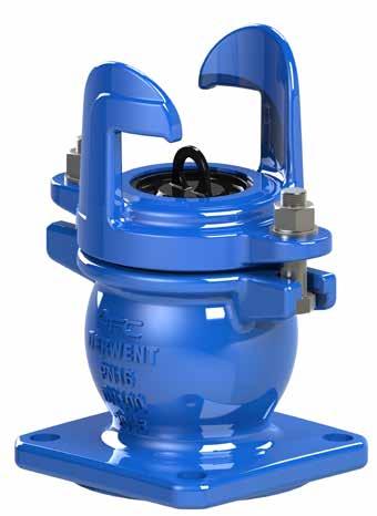
The Spring Hydrants are manufactured to AS3952-2002. The Spring Hydrants are available for both potable and non potable (reuse) applications.
Features and Configurations:
• Material: Ductile Iron body and top to AS1831.
• Coating: Fusion Bonded Epoxy (FBE) (or approved equivalent).
• Spring: 316 Stainless Steel.
• Brass Dome: To AS15568.
• Bolts, Nuts and Washers: 316 Stainless Steel (Anti galling coating).
• Connections: Potable and Reuse.
• Flanges: Table D.
• Pressure Rating: PN16 Only.
• Approval: Standards Mark License No: SMK40418.
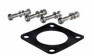
Note: Gaskets kits available upon request.

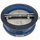
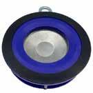
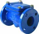
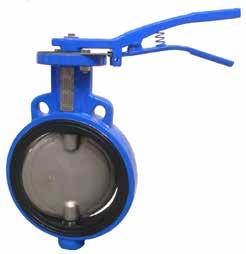
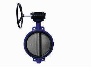
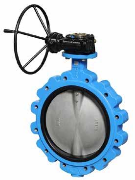
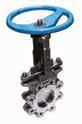
Resilient seat Butterfly Valves are used in a wide range of Industries including HVAC, gas, petrochemical, pulp and paper, water and wastewater treatment, brewing, food processing, mining, textile and general industry. They are compact and give bubble tight shut off as well as having good regulating capabilities.
Wafer Butterfly Style The body design is such that it can be used with most international flanges including AS2129, BS10, ANSI, DIN and JIS standards in sizes 50mm to 300mm. The wafer style is designed for inline service and relies on a flange either side of the valve to secure in the pipeline.
Note: Other Seats available upon request.
Note: Other Seats available upon request.
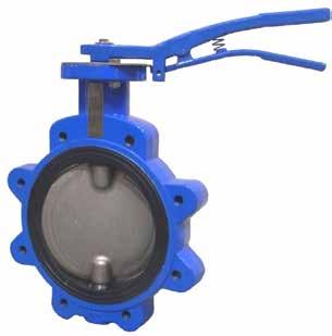
Resilient seat Butterfly Valves are used in a wide range of Industries including HVAC, gas, petrochemical, pulp and paper, water and wastewater treatment, brewing, food processing, mining, textile and general industry. They are compact and give bubble tight shut off as well as having good regulating capabilities.
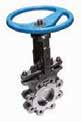
Lugged Butterfly Valves to suit Table D/Table E
• Compact lugged body.
• Metric tapped lugs cast into the body.
• Allows fixing of a flange one side at a time.
• Can be mounted at the end of a pipeline without the need for a flange on the downstream (discharge) side.
• Cold working pressure 1600kPa.
• Top flange compliant to ISO5211.
Note: Other Seats available upon request.
Note:
Note:

Stainless
Applications: Tailings, slurries,


Note: Other sizes available upon


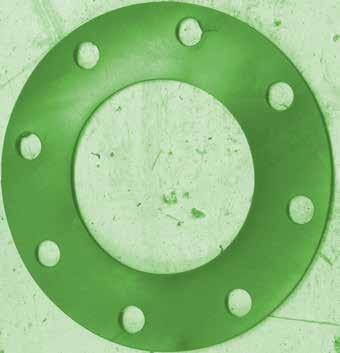
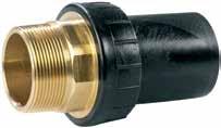
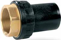
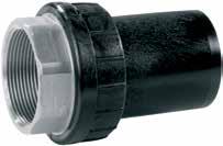
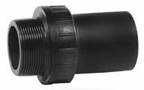
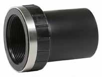
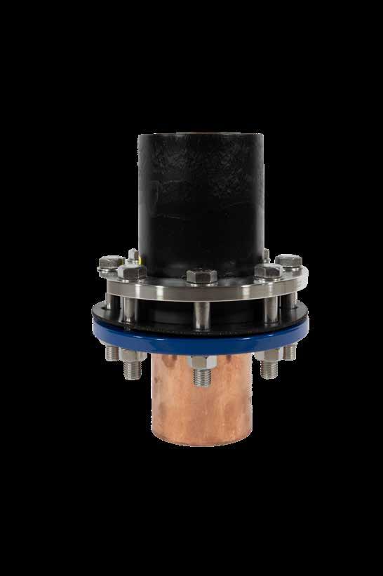
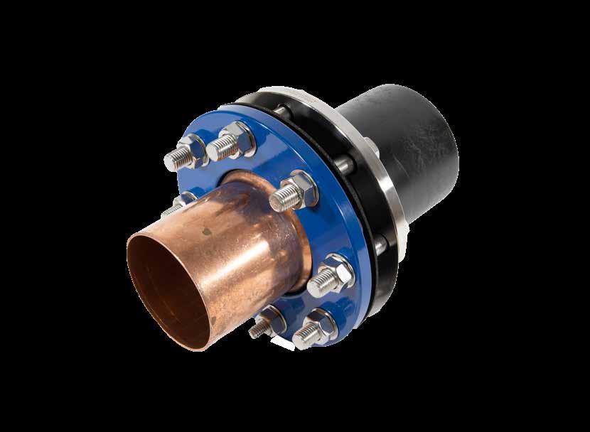
The Copamate flange adaptors have been developed to make life easier for the plumber, while saving time and money the unique flange coating means these adaptors do require rubber gaskets to prevent electrolysis.


922031 75/50 65/40
922032 75/56 65/50
922286 250/110 225/100
922287 250/125 225/115
922289 250/160 225/150
922290


Note: * With Stainless Steel Reinforcing Ring.

Note: * With stainless steel reinforcing ring.
7056004 25 x 20
7056005 25 x 25

Note: 15 NB Copper Kit fits any 20mm Plasson end. 20 and 25 NB Copper kit fits any 25mm Plasson end. The 15 and 20 NB Kit contains copper coloured nut, rubber liner, SS Ring and copper coloured cone. The 25 kit contains copper coloured nut, SS ring and coloured cone - rubber liner NOT required.
7990006 16 x 40
7990007 40 x 75
7990008 63 x 125
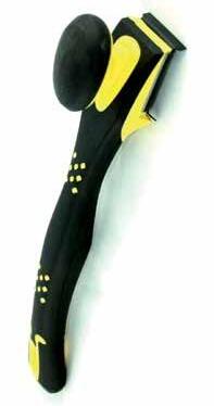
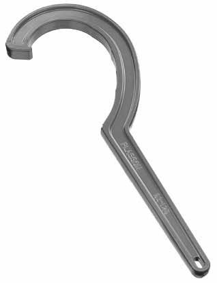
WARNING: For closing and tightening the PP nuts of Plasson fittings. It is important when closing the nut on Plasson fittings that the nut is NOT OVERTIGHTENDED as the nut can be deformed - this may result in a pipe blowing or pulling out of a fitting. Hand tighten and a further 1/2 turn with the wrench. For rural 1/2-2” and metric 16-32mm a wrench is not needed. Firmly hand tighten.
7960001 20 - 63
7960002 Blade for Chamfer Tool
WARNING: For overall pipe diameters from 20-63mm. Operates like a pencil sharpener. Chamfering and lubricating pipes from 40-63mm, eases jointing pressures.
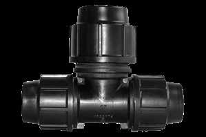
63 x 25 2234.6325
63 x 32 2234.6332
90 x 25 2234.9025
90 x 32 2234.9032
110 x 25 2234.1125
110 x 32 2234.1132
125 x 25 2234.1225
125 x 32 2234.1232
160 x 25 2234.1625
160 x 32 2234.1632
180 x 25 2234.1825
180 x 32 2234.1832
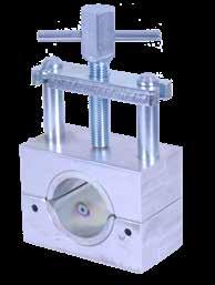
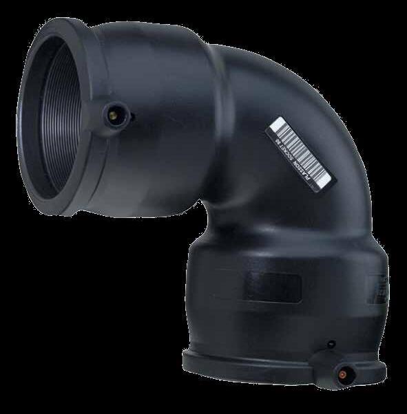
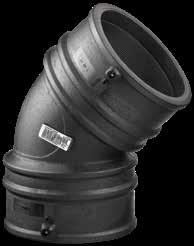
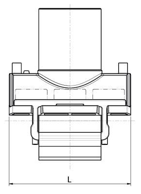
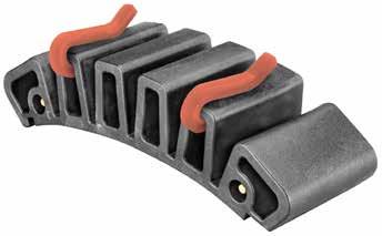
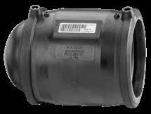
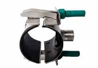
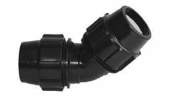
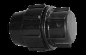
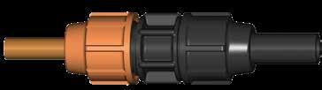
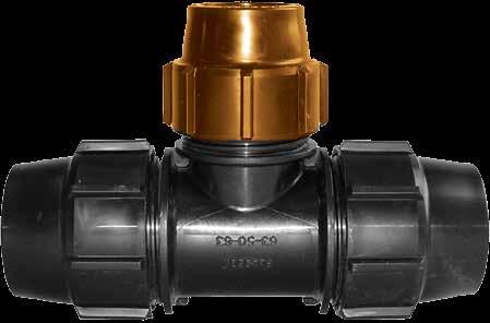
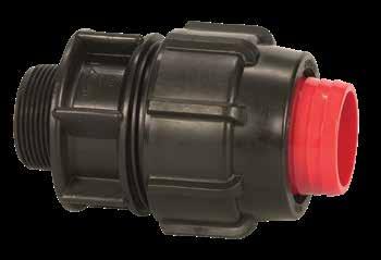
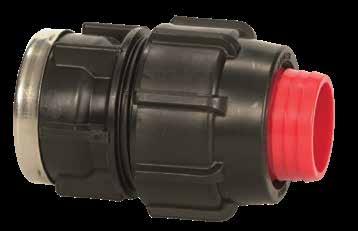
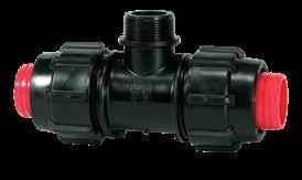
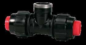
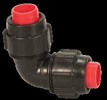
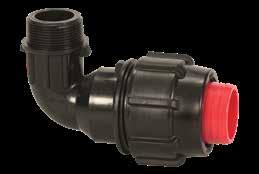
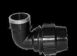
• Fast and innovative tightening mechanism.
• No bolts.
• Non-corrosive, strong and durable plastic parts - no metal components.
• Integral seals - no need for thread sealants.
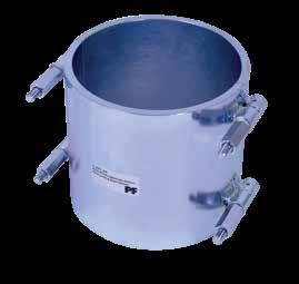
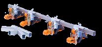
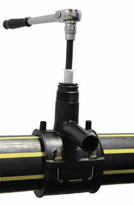
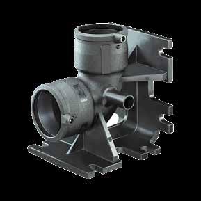
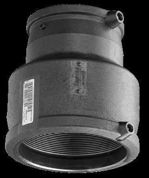
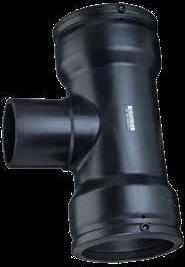
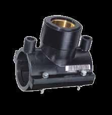
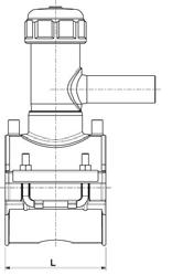
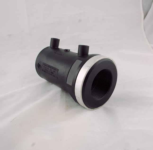
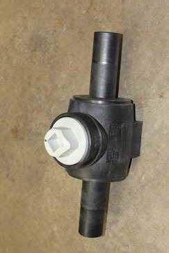
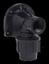
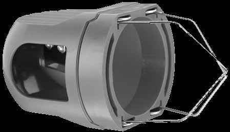
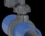
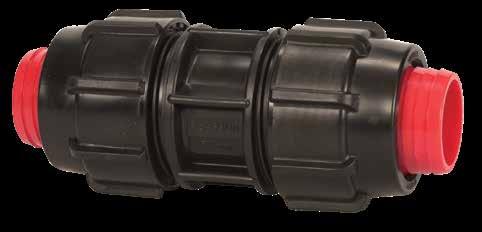
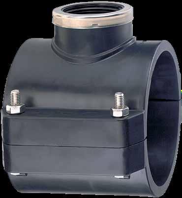
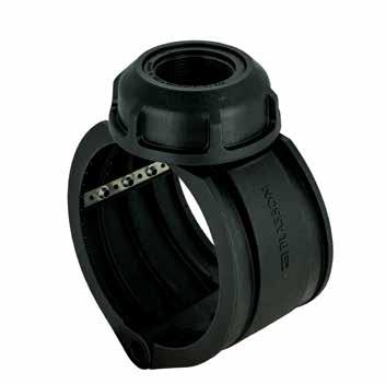
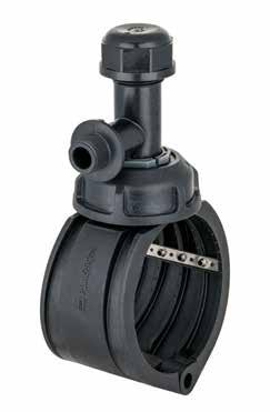
"Plassaddle" – Plasson's revolutionary mechanical saddle
Plasson is proud to introduce its newly designed mechanical saddle, featuring fast, bolt free installation as well as some of our well-established mechanical fitting features:
Plasson is proud to introduce its newly designed mechanical saddle, featuring fast, bolt free installation as well as some of our well-established mechanical fitting features:
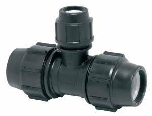
The Saddle is available in three versions
Fast and Innovative tightening mechanism
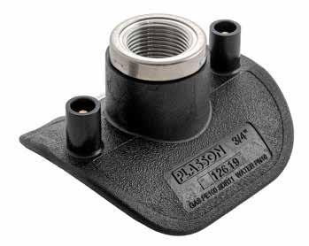
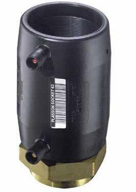
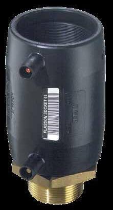
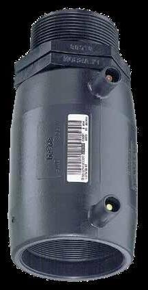
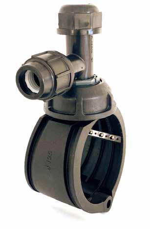
1. Female threaded offtake (ISO 7-1 “Rp” thread), in sizes 1/2”, 1”, 11/4” and 11/2”.
No bolts
Plasson is proud to introduce its newly designed mechanical saddle, featuring fast, bolt free installation as well as some of our well-established mechanical fitting features:
Plasson is proud to introduce its newly designed mechanical saddle, featuring fast, bolt free installation as well as some of our well-established mechanical fitting features:
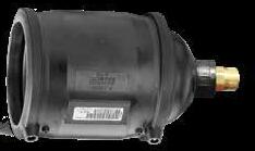
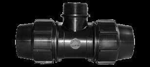
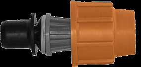
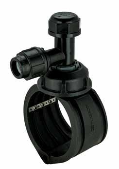
2. “Live” Tapper body with integral 25 or 32mm Series 7 compression ends for connection to PE service pipes.
Fast and Innovative tightening mechanism
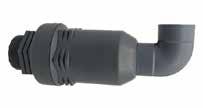
3. “Live” Tapper with 3/4” male thread (ISO 7-1 “R” Thread).
No bolts
Non-corrosive, strong and durable plastic parts – no metal components
Fast and Innovative tightening mechanism
Technical specifications
Integral seals - no need for thread sealants
Fast and Innovative tightening mechanism
No bolts
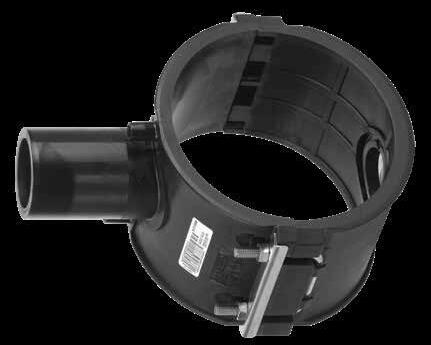
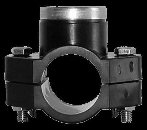
• Suitable for use on PE pipelines between 63 and 180mm OD and a range of PVC S1 and S2 pipe diameter.
Non-corrosive, strong and durable plastic parts – no metal components
No bolts
Integral seals - no need for thread sealants
• PN16 pressure rating.
Non-corrosive, strong and durable plastic parts – no metal components
Non-corrosive, strong and durable plastic parts – no metal components
Raw materials: PP + GF clamps, PPB body, EPDM
Integral seals - no need for thread sealants

Integral seals - no need for thread sealants
2

the
The
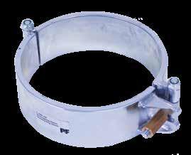
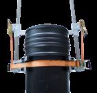
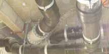
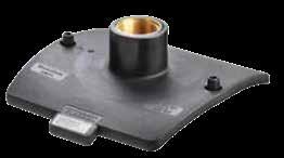
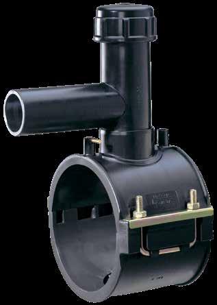
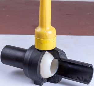
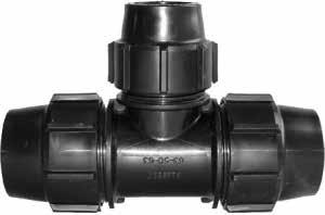
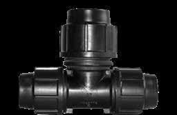
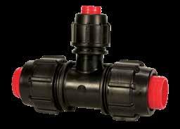
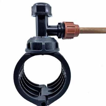
After the main retaining nut is tightened by hand, a Plasson Line 7 spanner is used to rotate the nut another 1/2 turn and firmly secure the saddle in place. 1
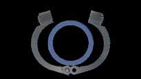
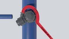
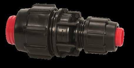
The two clamps of the saddle wrap around the pipe and snap together. The saddle is now retained on the pipe and the installer is free to keep working.
of the saddle wrap around the
and snap together. The saddle is now retained on the pipe and the installer is free to
The two clamps of the saddle wrap around the pipe and snap together. The saddle is now retained on the pipe and the installer is free to keep working.
After the main retaining nut is tightened by hand, a Plasson Line 7 spanner is used to rotate the nut another 1/2 turn and firmly secure the saddle in place.
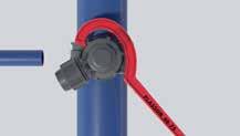
After the main retaining nut is tightened by hand, a Plasson Line 7 spanner is used to rotate the nut another 1/2 turn and firmly secure the saddle in place.
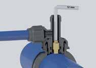
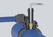
and PVC pipe mains is achieved by operating the integral cutter with a 12mm hex drive.
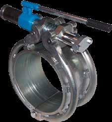
direction tightening the grey nut by hand. The outlet may still have a small amount of movement after the grey nut is tightened - this is OK as internal 'O' rings prevent sealing. unpressurised
The outlet is secured in the desired direction tightening the grey nut by hand. The outlet may still have a small amount of movement after the grey
The outlet is secured in the desired direction tightening the grey nut by hand. The outlet may still have a small amount of movement after the grey nut is tightened - this is OK as internal 'O' rings prevent sealing. Tapping of either live or unpressurised PE and PVC pipe mains is achieved by operating the integral cutter with a 12mm hex drive.
Tapping of either live or unpressurised
RURAL X BSP
7030015 2" x 11/2”
7030016 2" x 2"
Note: * Fitting with Stainless Steel Reinforcing Ring.
Note: Use to seal any
2" x 1" 7150015 2" x 11/4” 7150014 2" x 1"
7150015 2" x 11/4
Note: Fittings with threads 11/4” and above have a
Note:
1607001
1607002
1607011
Note:

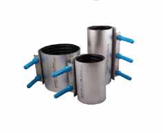
Note: The nuts and bolts are made of galvanised steel. O-Rings are NBR rubber. FPM and EPDM O-Rings are available subject to special pricing and delivery. Bolts galvanised via electroplating then protected with a proprietary passivation process. For buried applications, use Stainless Steel nuts and bolts.
Note: The nuts and bolts are made of stainless steel. The O-Rings of NBR rubber. O-Rings can be supplied as FPM and EPDM, but are subject to special pricing and delivery.
5160001
5160004
5160005
5160006
CODE SIZE (mm)
5170001 3/8"
5170002 1/2"
5170003 3/4"
5170004 1"
5170005 11/4"
5170006 11/2
5170007 2"
CODE SIZE (mm)
5070001 1/2"
5070002 3/4"
5070003 1"
5070004 11/4"
5070005 11/2"
5070006 2"


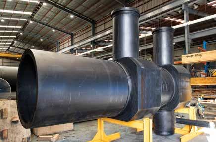
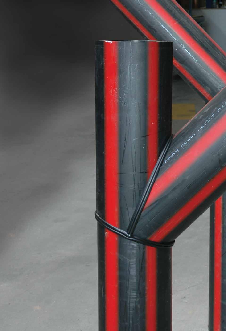
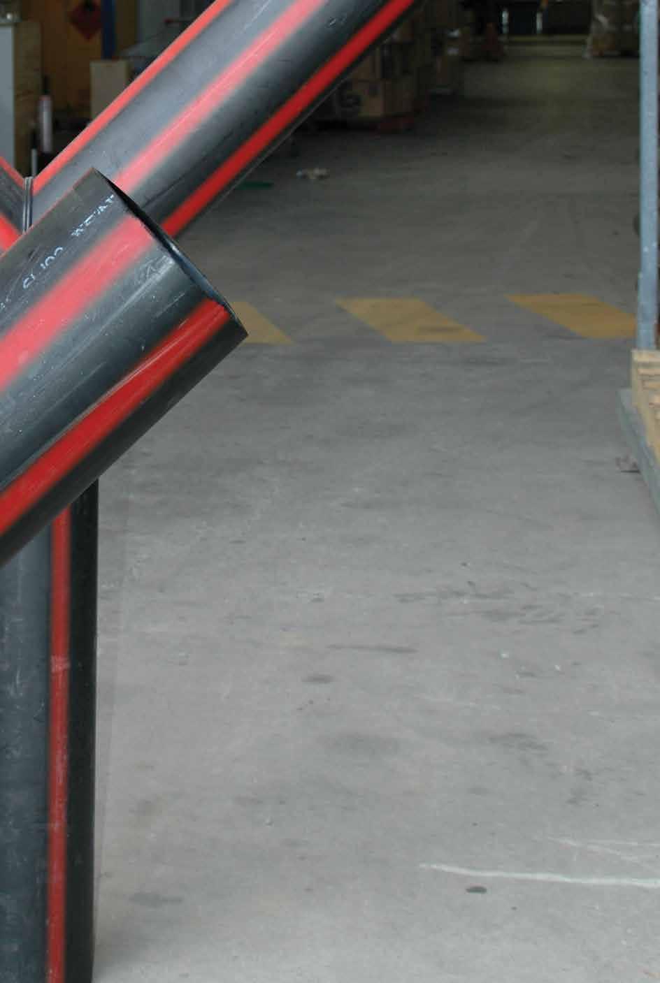
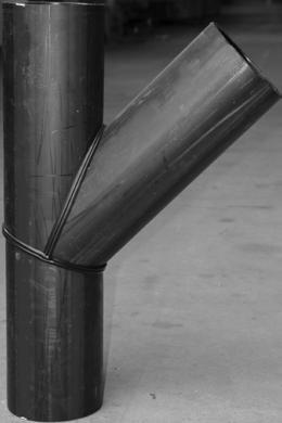
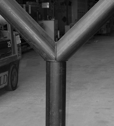
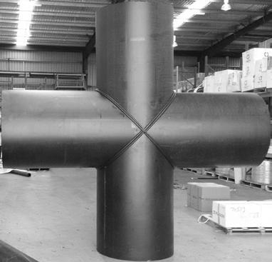
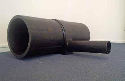
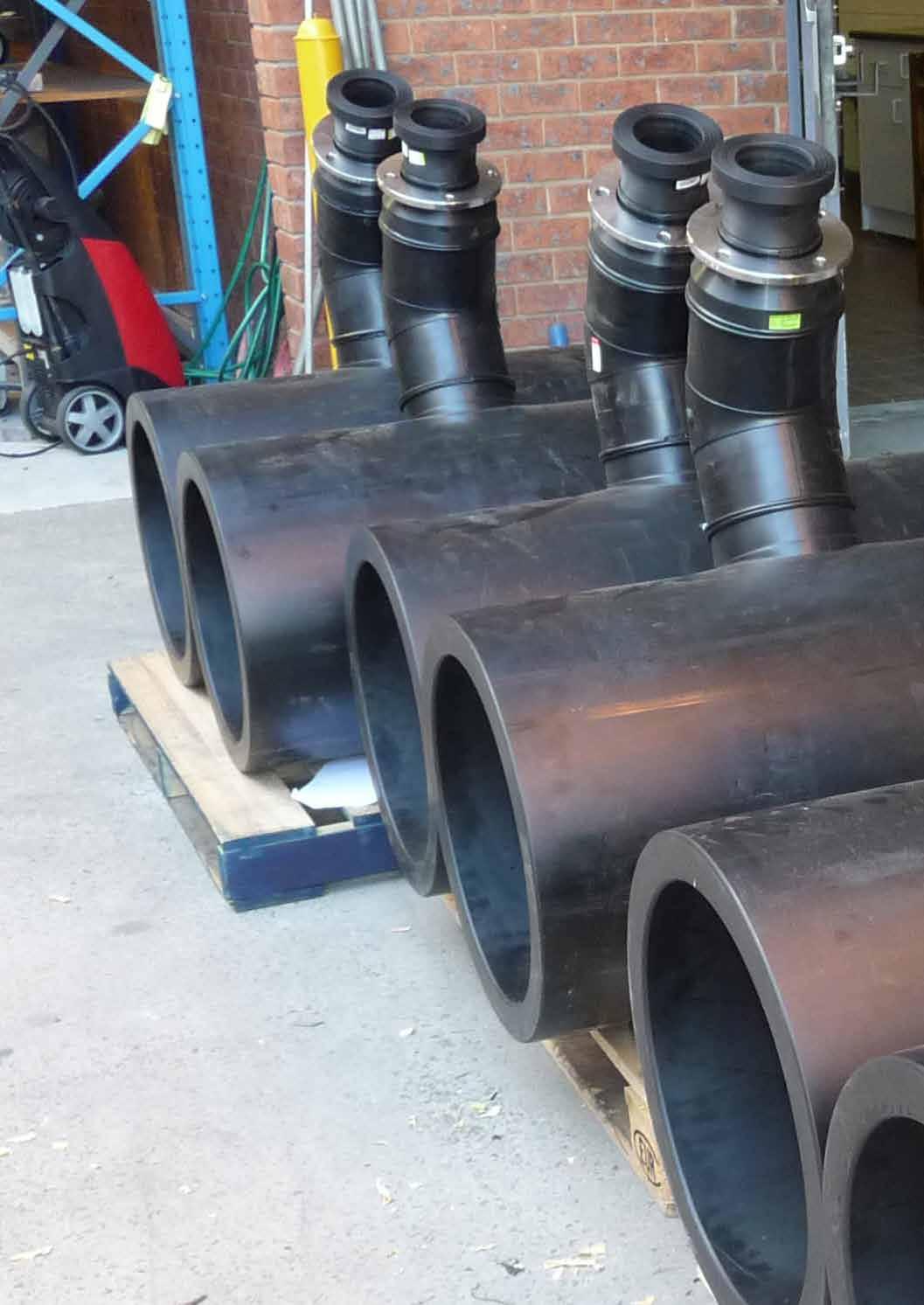
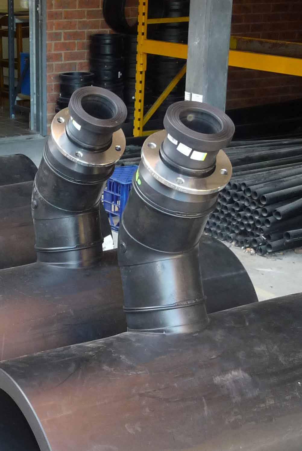
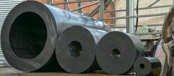
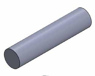
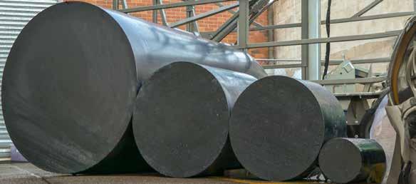
ADROIT Piping Systems offers custom and specialised fittings including fully pressure rated tees, junctions and flanges machined from solid and hollow bar. Our versatile and innovative fabrication department is able to design the most cost effective and sustainable solutions for the project at hand. Should you require further information, please do not hesitate to contact our technical sales team on 1300 004 373.


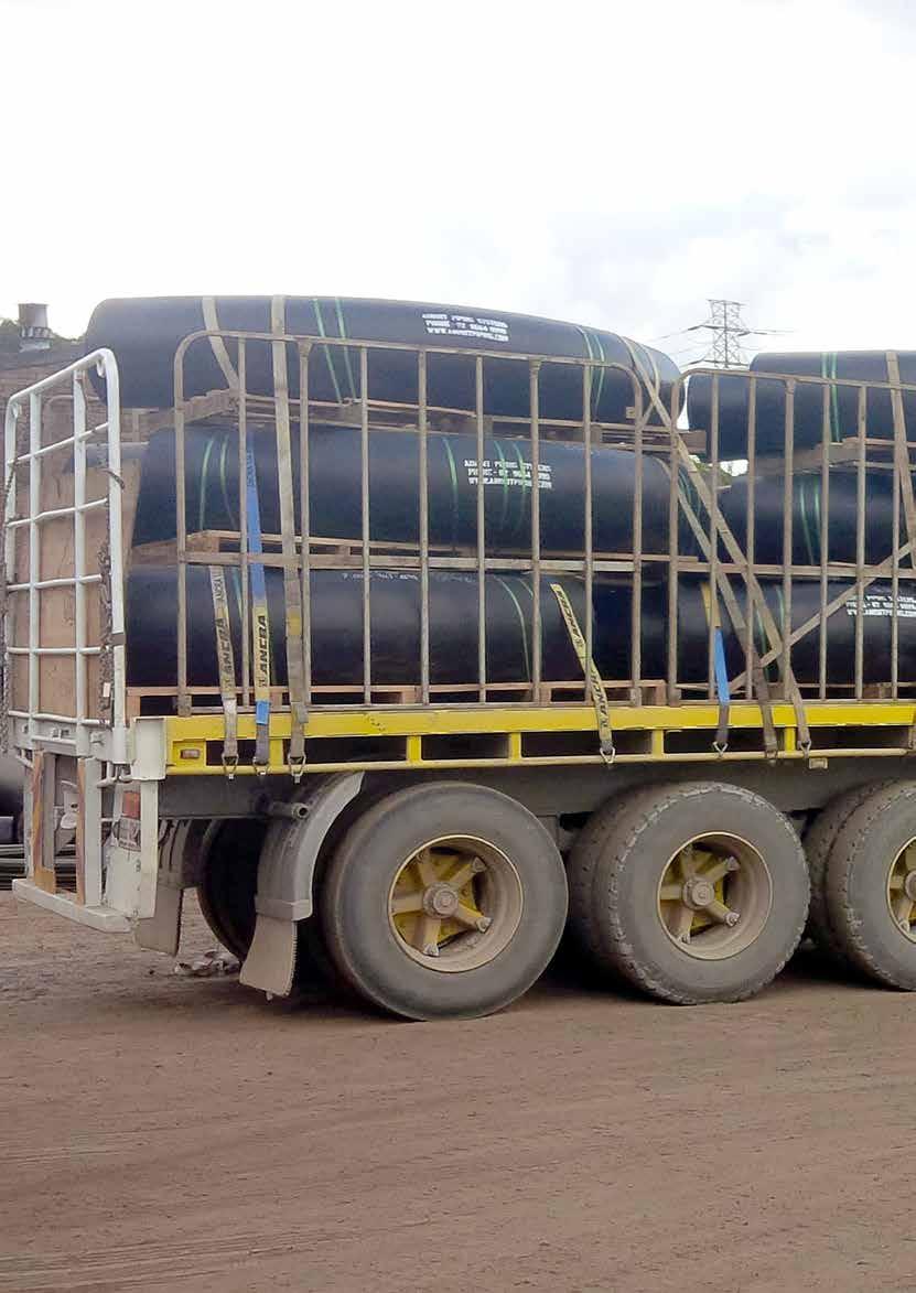
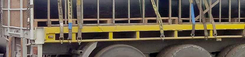
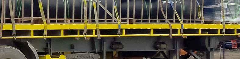
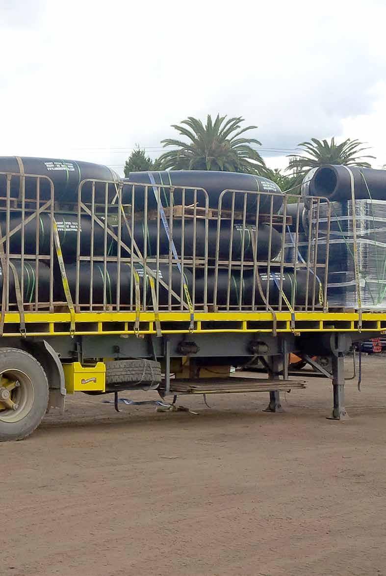
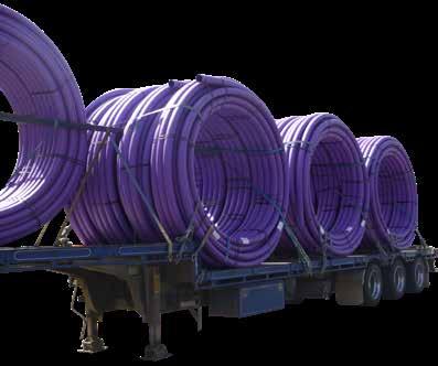
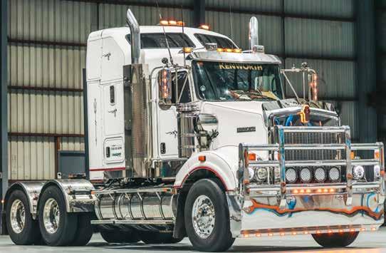
Note: This information is provided as a guide only. Our transport team have decades of experience, so call us today for advice on your project logistics.
PE100 pipes may be bent or curved on site. The minimum bend radius for SDR11 and SDR17 pipes is 25 times the pipe OD, increasing to 35 times the pipe OD in very cold weather. For thin-walled SDR26 and SDR33 pipes, these values should be increased by 50%. Thicker walled pipes require special consideration, please contact us for more information. Electrofusion or mechanical joints and fittings should not normally be incorporated in sections of pipework which are to be bent. Instead a formed bend or elbow should be welded into the pipeline in order to prevent excessive stress. The use of pegs or stakes in the trench to define the radius of the designed curve, or to restrain the pipe during installation, is not permitted. Bending tends to be localised at the pegs or stakes and, if they are left in the trench when it is filled, highly localised stresses may cause premature failure of the pipeline.
– May be used for all applications except for fuel gases
– Drinking Water – Fuel gases, process gases, liquified gases under pressure
– Dedicated water for fire extinguishing supply lines
– Communications conduit
– Recycled or reclaimed water
– Electrical conduit
– Above ground pipelines
NOTE: The minimum life periods may be considered to be the minimum potential service lives and represent the maximum extrapolated periods permitted by the ISO 9080 extrapolation rules given the available test data.
OBLIGATION
Adroit Piping Systems recognises its moral and legal responsibility to provide a safe and healthy work environment for employees, contractors, customers and visitors. The organisation commits to eliminating work-related injury and illness. This commitment extends to ensuring that the organisation’s operations do not place the local community at risk of injury, illness or property damage.
OBJECTIVES
Adroit Piping Systems will:
• Provide a safe workplace for workers.
• Ensure all equipment is safe for use by workers.
• Provide procedures and instructions to ensure safe systems of work.
• Provide information, instruction, training and supervision to employees, contractors and customers to ensure their safety.
• Ensure continual compliance with legislative requirements and current industry standards.
• Ensure OHSMS remains effective in providing a safe place of work for all employees and visitors.
• Ensure communication methods with employees remain effective.
• Maintain Health Surveillance practice and records.
RESPONSIBILITIES
Each management representative is accountable for implementing this policy in their area of responsibility. Management is responsible for:
• The provision and maintenance of the workplace in a safe condition.
• Involvement in the development, promotion and implementation of health and safety policies and procedures.
• Training employees in the safe performance of their assigned tasks.
• The provision of resources to meet the health and safety commitment.
• Provide support and assistance to employees.
• Review periodically to ensure the health and safety policy remains related and applicable to the organisation.
Employees are to:
• Follow all health and safety policies and procedures.
• Report all known or observed hazards to the WHS representative or their immediate supervisor.
APPLICATION OF THE POLICY
This policy is applicable to all operations. It is endorsed at all levels and displayed at all work locations.


Adroit Piping Systems specialises in the manufacture and supply of innovative piping systems and parts to the piping industry and utilities supplier sector.
OBJECTIVES
The organisation is committed to achieving excellence and continued improvement by providing the highest quality products and services to clients. To achieve this, and to satisfy customer expectations, the organisation is totally committed to implementing, maintaining, and improving our Quality Management System based on ISO 9001:2015.
The organisation aims to:
• Reduce non-conformances in manufacturing.
• Improve customer experience.
• Better manage operational risks and opportunities.
• Maintain and improve the capabilities of all equipment.
• Maintain and improve employee competencies and working efficiency.
Quality issues arising in various areas shall be identified and solved quickly, efficiently and economically in a systematic manner. The organisation shall focus our resources, both technical and human, towards the prevention of quality deficiencies in order to satisfy the organisational goal of “right first time… every time”.
The successful implementation, operation, maintenance, and improvement of our Quality Management System relies on the co-operation and involvement of personnel at all levels.
All levels of management hold a responsibility for the Quality Management System. Management shall ensure that the organisation continues to strive towards achieving its quality objectives. Management shall also demonstrate good leadership, as it is integral to the success of the Quality Management System.
Employees play a vital role in ensuring that all quality-related procedures are followed in all aspects of their work. All employees are also responsible for consulting with relevant persons when any issues arise that may affect the quality of the products or services.
This policy is applicable to all operations. It is endorsed at all levels of the company and displayed at all work locations.