

Selected Works | 2020-2024 | Abhay Khele
ABOUT ME:
Hello, I’m Abhay, and I’m keen about combining my passion for technology and science with the field of architecture. Eager to embark on a path of learning and applying my passions into unique design approaches.
My architectural philosophy is influenced by Schrödinger’s cat experiment. Architecture, like the cat, exists in a state of fluctuation until it is observed. I enjoy unraveling each project’s unique narrative as it progresses from abstract to tangible, embracing the unpredictability of the creative process.

Abhay Khele
Email: abhaykhele1@gmail.com
Contact no.: +91 8999236049
Linkedin: Linkedin.com/in/abhaykhele
Instagram: abhay. .khele
Education:
2010-2018
2018-2019
2020-2025
Sona “i” English Medium School, Pune
MES Abasaheb Garware College, Pune
SMEF’s Brick School of Architecture, Pune
Work Experience:
2021
2022
2024 2024
Intern at Tres Atelier (2 Months)
Brick Magazine Graphics Head
Research and Publication Intern at Brick School of Architecture (6 Months)
Student team lead for Pet Park Project alongside PMC-BRADCL (Being Built at Katraj, Pune)
Competitions:
GRIHA 2023 (Top 10 Shortlisted)
GRIHA 2022 (Top 16 Shortlisted)
ANDC 2022 (Top 7 Shortlisted)
AIS Olympiad
CASA
Lauri Baker Trophy
ETHOS
Marsception
Unfold 3.0
Core Strengths:
Design Analytics
Conceptulization
Software skills
Photogrametry
Lazer Cutting
3D Printing
Soft Skills:
Teamwork
Problem solving
Critical Thinking
Creativity and inovation
Patience
Positive Attitude
Self Motivation
Emotional intelligence
Attention to detail
Keen-Learning
Personal Interests:
Digital Art
Character Design
Origami Technology
Astro-Physics
Music
Bussiness

Exposure:
ACEDGE Beyond BHK where Anupama Kundoo was a mentor.
Brick 12on12
ICOMOS Publication on Kudase Village
Stepwell Documentation at Parner, Ahmadnagar
Leewardists Comic making workshop
Resin Workshop at NASA’s 65th ANC
Udupi-Adaptive Reuse
Facade Design Elective
Softwares:
AutoCad
Sketchup
Rhino
Photoshop
Powerpoint
Excel
Indesign
Illustrator
Lumion
Revit
Vray
Agisoft Metaface
Grasshopper
Ultimaker Cura
Languages:
English
Marathi
Hindi
Proficiet
Proficiet
Proficiet
Proficiet
Proficiet
Proficiet Efficient Efficient Efficient Efficient Efficient Learning Learning Learning
German Proficiet Proficiet
Publications:
Proficiet Basic
Brick Newspaper (August 2023)
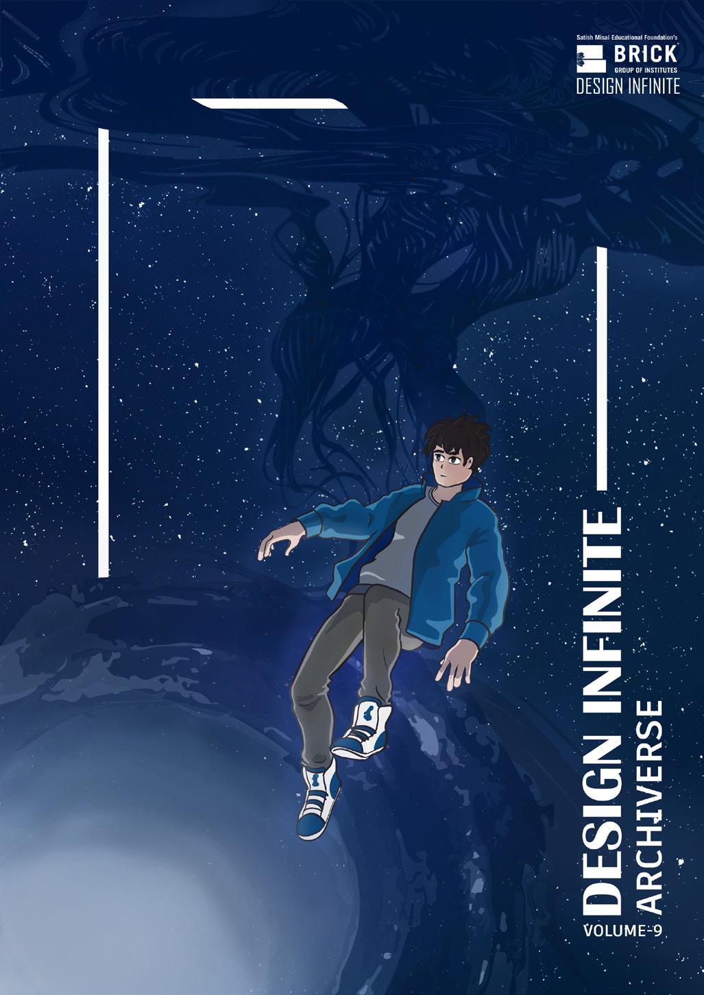
Design Infinite: Archiverse (Brick Magazine Vol-9)
Aparanta: Deciphering Sindhudurg (Book)
Whispers of Sacred Ruins (Book)
Urban Voids (Book)
Historic Courtyard (Reserch paper)
CON TEN TS

1 Kalpataru
Jejuri-Morgaon Highway, Pune School and Multipurpose Hall
2 The Urban Cascade Mitramandal Chowk, Swargate, Pune Urban Habitat
3 Neoasis
Jamalpur, Ahemdabad Luxury 5 Star Hotel
4 Queen Alia International Airport Amman, Jordan Long-span roof Redesigning
5 The Twist
Palm Jumeirah, Dubai Highrise Steel Structure
6 Samuday Bhavan Kudase, Konkan Community Empowerment Campus
7 Lumos
Modular Facade Prototype Office Buildings
8 Extras Working Drawings And Technical Projects Photography And Artworks
1
Kalpataru
Jejuri-Morgaon Highway, Pune 3D Printed School and Multipurpose Hall
This project is a beacon of education for underprivileged children. Inspired by India’s Gurukul system, it provides holistic education in an uplifting ambiance. The revolutionary 3D printing construction of its walls demonstrates sustainability and efficiency. Symbolic tree-like roofing provides protection while encouraging a connection with nature. This project unites diversity, tradition, and forward-thinking design, giving students the tools they need to succeed.

Site Context:
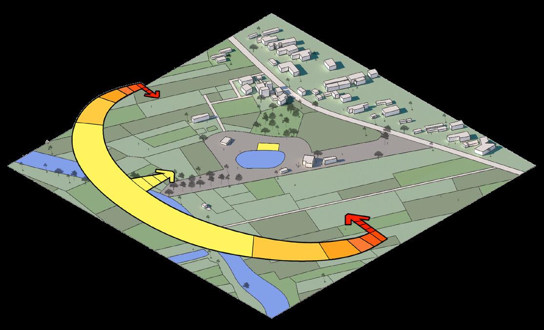
The larger site is located on the Jejuri-Morgaon highway. The Built site is located between the large area of land owned by a single owner.
Orientation of the site is at at 55 degree angle to the north and is surrounded by a lake and forest.
There is a school named Kudachi shala inside the main site. The site has open space on one side and lawn on the other side.

Hexagonal Striaght Sections
Quadrilateral Striaght Sections
Quadrilateral Hyperbolic Sections (Finalised)
Hexagonal Hyperbolic Sections
Truss Options
Plan A A’
Perspective Cut Section A-A’
Polycarbonate sheets
Glass Skylight Exploded
Stanchions and Trusses
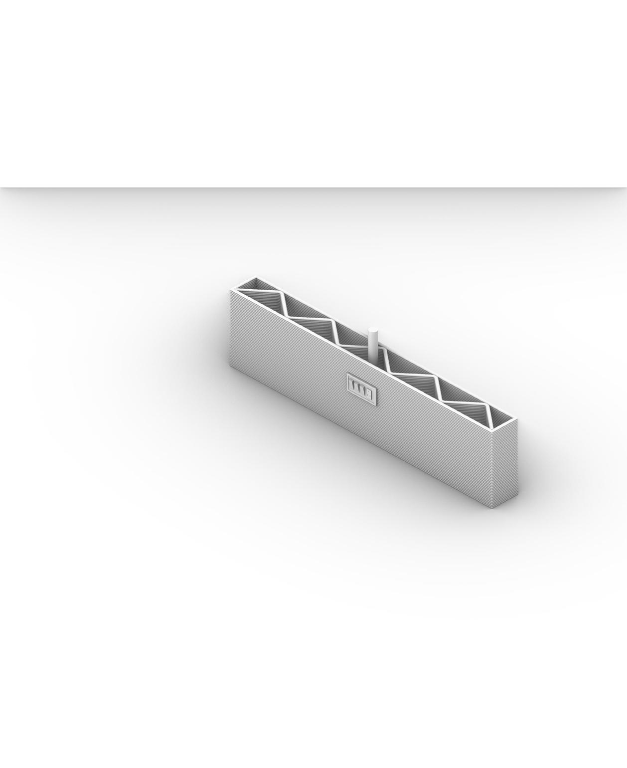
Electrical Conduiting
Cavity For Services
3D Printed Concrete With Nossel Width 50mm
Polycarbonate sheets
Stage
Piviot Windows
3D Printed Walls
Electrical Switch Boards
Infill For Strength
3D Printed Wall Detail
UV resistant polycarbonate sheets 10mm thick
150x50 mm C-section ms purlins
12mm thick plate
50 mm dia hollow pipe trusses
25 mm dia hollow pipe trusses
8mm thick Truss base plate
4nos. 65mm dia hollow pipe compound stanchion
25mm dia hollow pipe lacing
Anchor Bolts
8mm thick Stanchion base plate
400X550mm RCC pedestal
Plinth
View Steel Detail
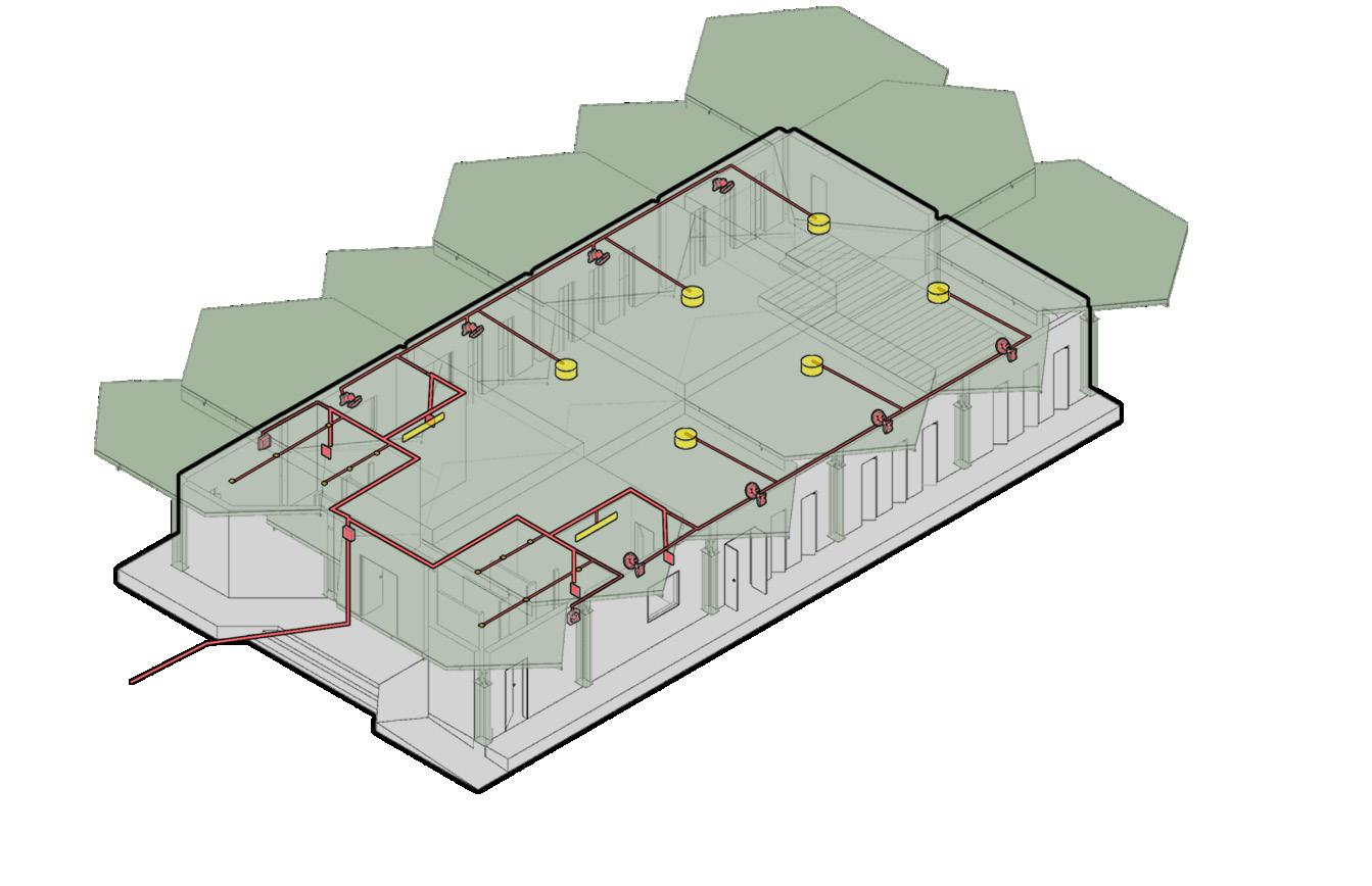
Water layout:
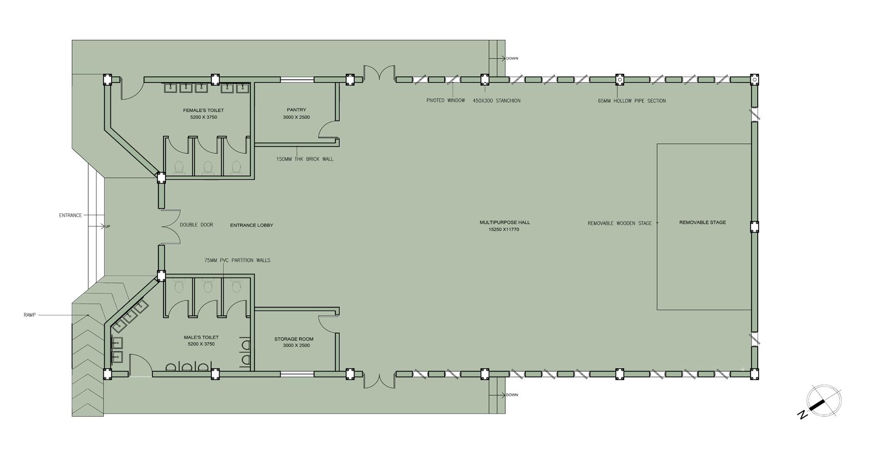
Water requirement for each person - 15 Liters
No. of occupants considered - 100
Water Consumption- 100 X 15 = 1500 LIiters
For OHWT - 1500 + (10 X 15) = 1650 Liters
So size is, 2000 X 1500 X 500 mm
For UGWT - 2475 Liters= 2.475 m cube
So size is,2500 X 1000 X 1000 mm
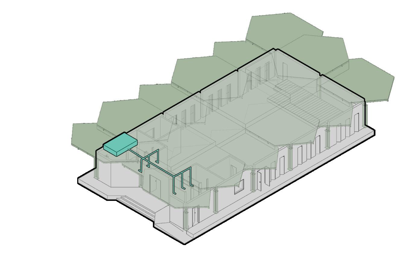
Eletrical layout:
The electric layout of the hall is done on the basis of no of fans and lights required.
Exhaust fans are provided at the toilets and wall mounted ceiling fans are provide in the hall.
To provide light in the hall at night hanging lamps are provided in the hall and tube lights are provided in the other rooms.
Septic Tank
Inspection Chamber
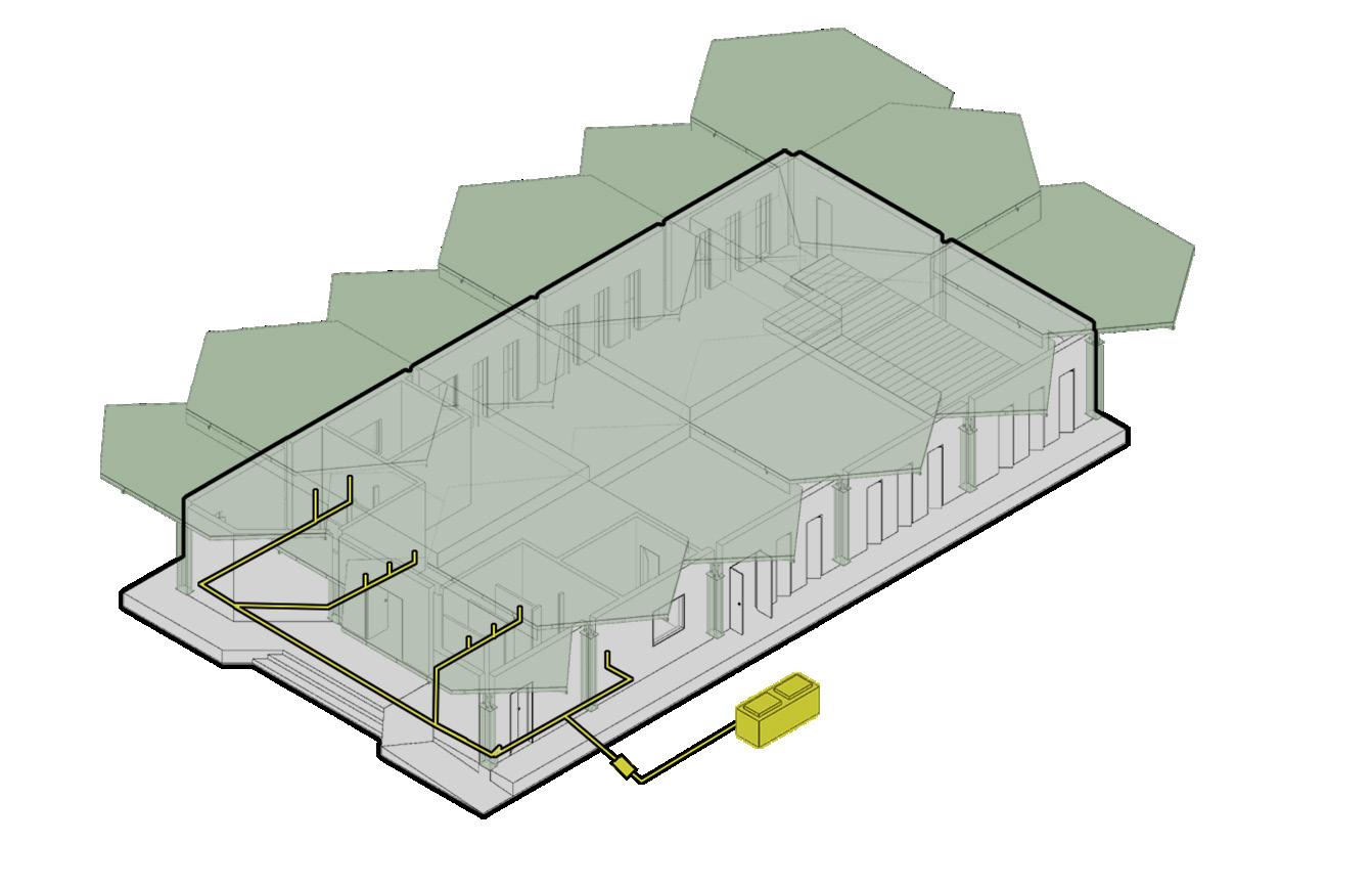
Plumbing layout:
Bathroom Fixtures
Water Tank
Plumbing system needs to be connected to the sewage line of the city.
In this project we are proposing a septic tank instead of disposing the waste into the city’s sewage system.
This helps in disposing off waste as well as to provide manure for the landscaping proposed at the site.
MCB
Drop
Down Lamps
Tube Lights
Switch Board
Wall Mounted Fans
2
The Urban Cascade
Mitramandal Chowk, Swargate, Pune Urban Habitat
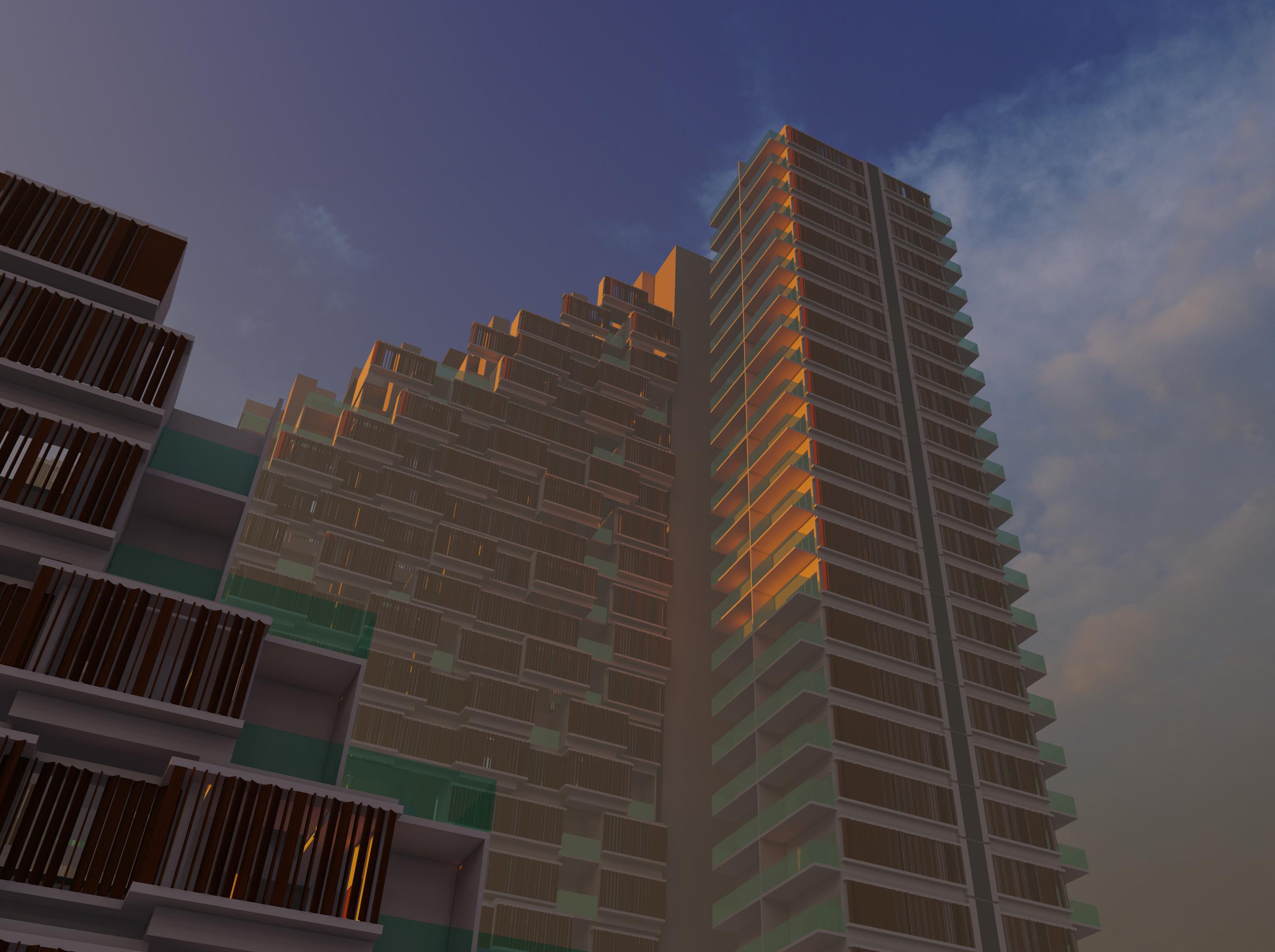
A modern vertical housing project, seeks to rethink urban life for 400 tenements. This project seamlessly blends form and function, with a distinctive stepped design centered on a communal podium. It embraces the city’s energy by integrating cascading galleries to provide inhabitants with stunning views and public areas that defines a whole approach to contemporary society that prioritizes both beauty and functionality.
Site Context:
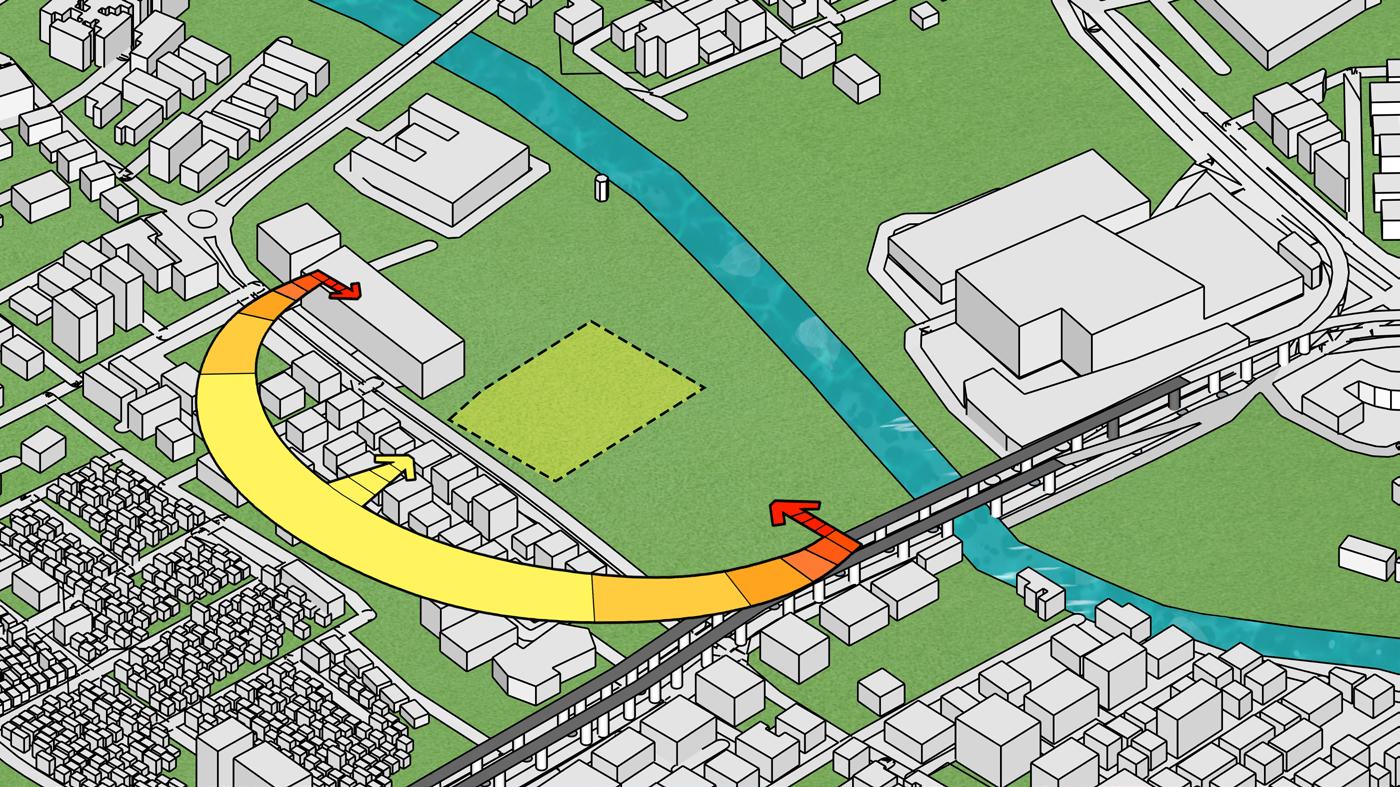
The Site is located near Mitramandal Chouk, Swargate. A small water cannal is located towards the north of the site and swargate flayover towards the east.
Orientation of the site is at at 5 degree angle to the north and is surrounded by Dense vegetation.
The upcoming swargate Metro station is located towards the north east of the site and residential area towards the south.
There is a HCMTR being proposed on the north side and the site comes under the TOD area.
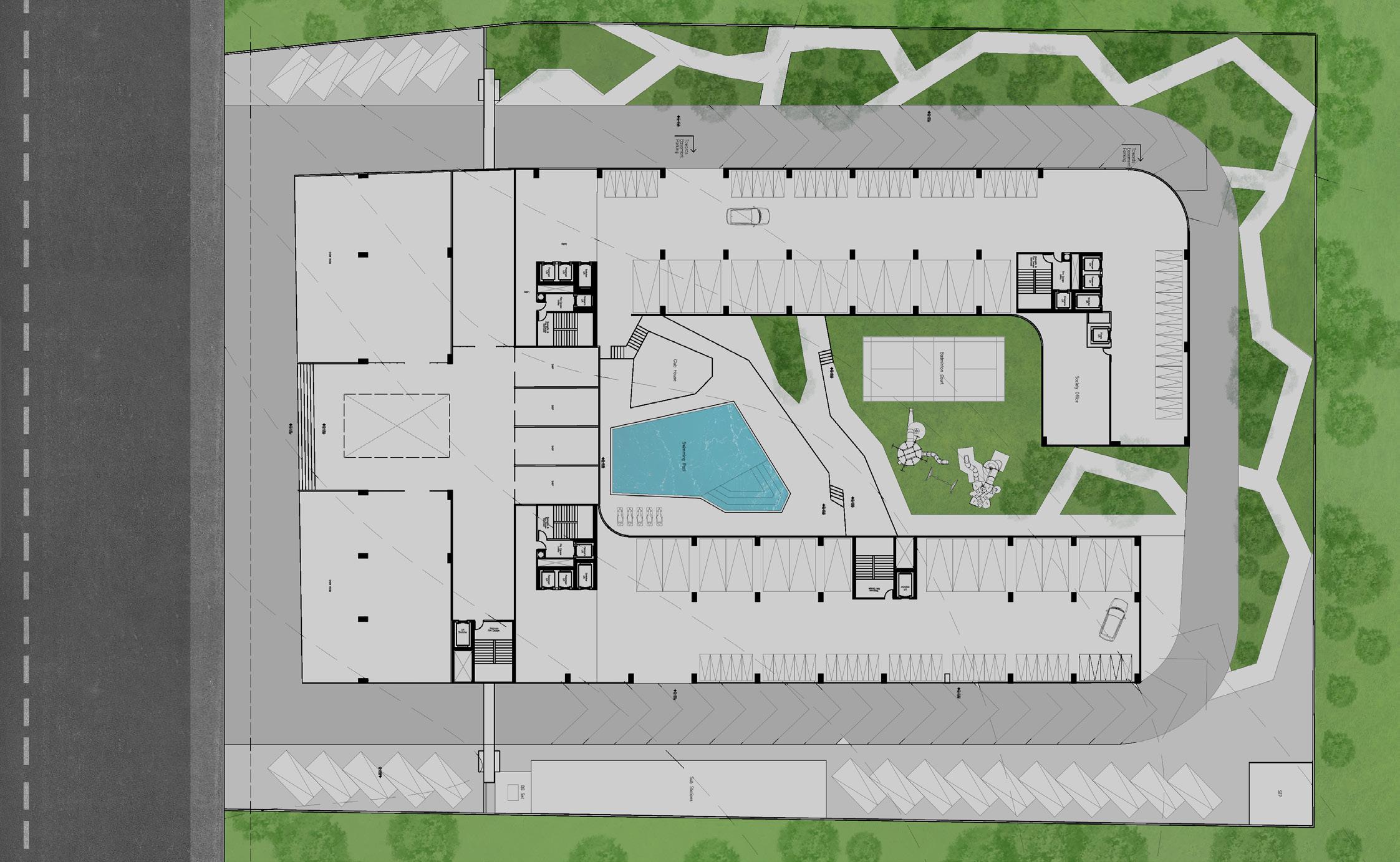
Site Plan
22 m wide road
of Appartments Massing According to the FSI requirements Dividing on north-south axis Creating central Skylight Making slit towards north to let in light Stepping to create Multiple viewpoints
cores Basements Commercial Block
Light
Form Development Stacking
Building
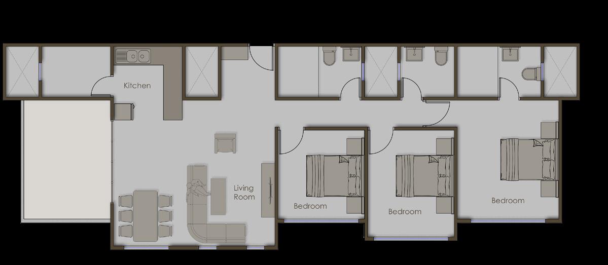
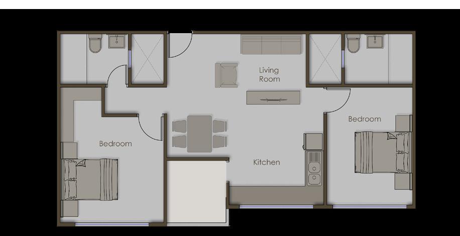
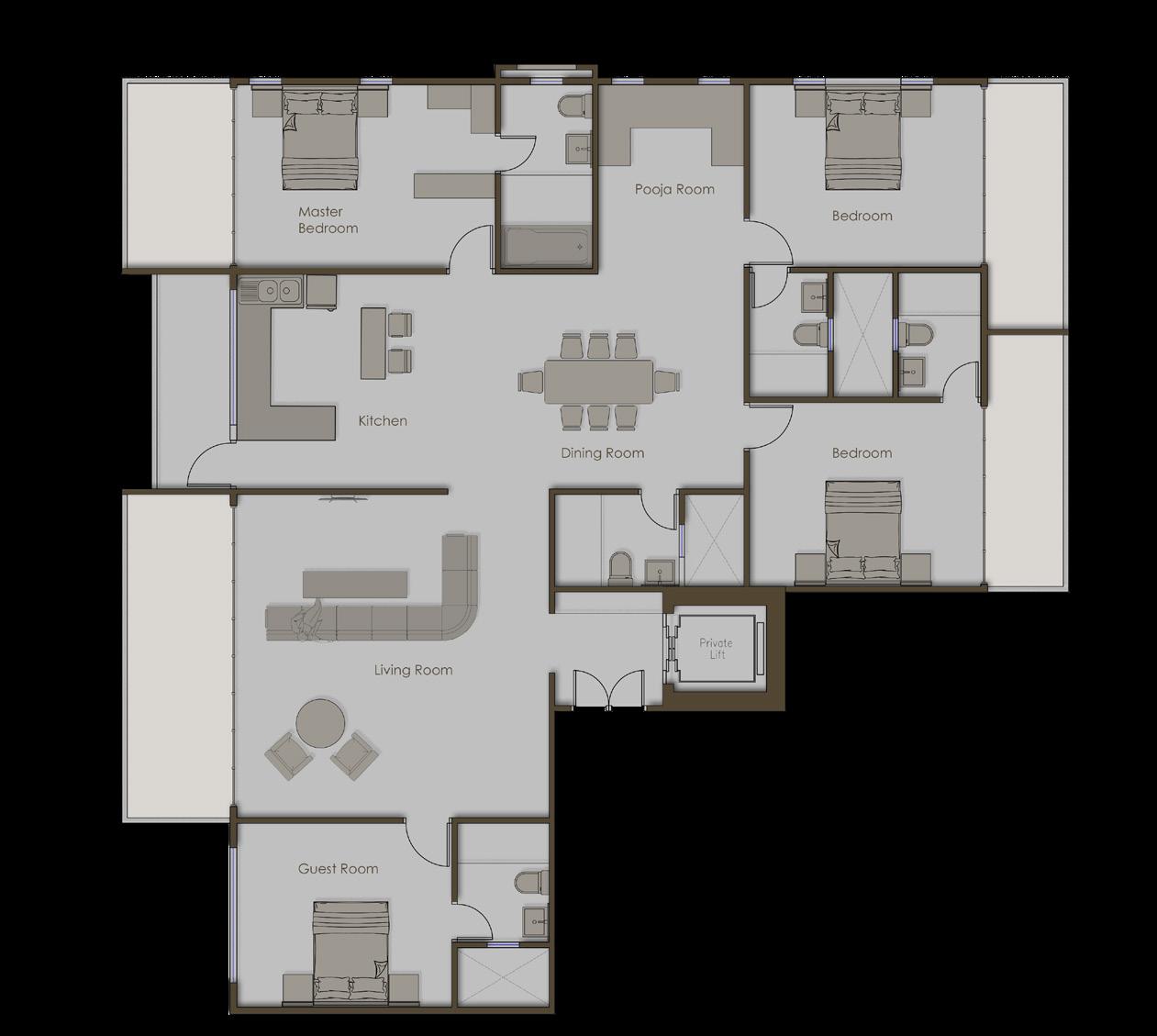
5-Room Appartments Voids for
4-Room Appartments Studio Appartments 2-Room Appartments 3-Room Appartments
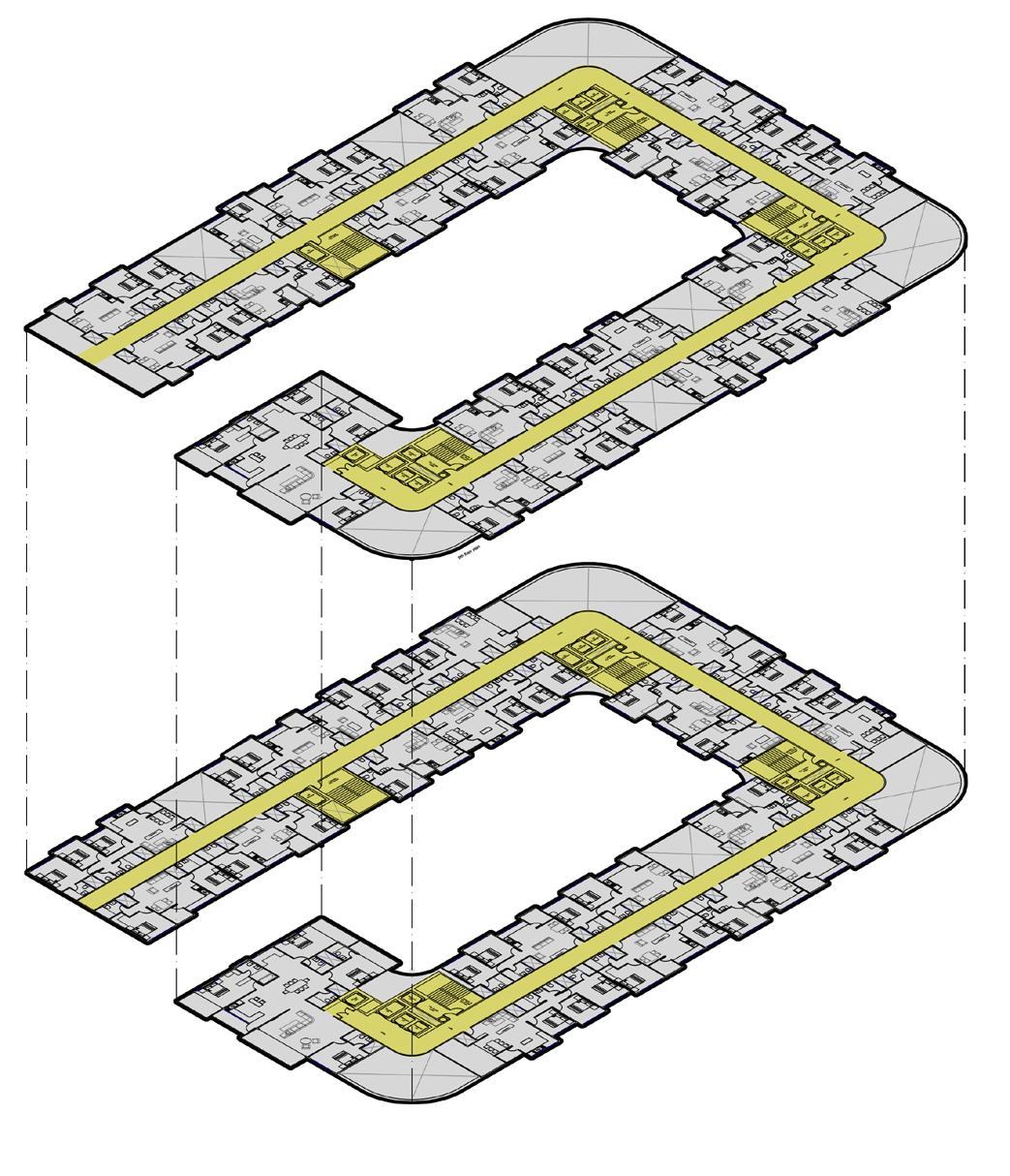

Type of Appartments Stacking of Floorplates 5-Room Appartments 4-Room Appartments 3-Room Appartments 2-Room Appartments Studio Appartments 9th Floor Level 8th Floor Level Area, FSI and Parking Calculations
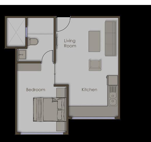
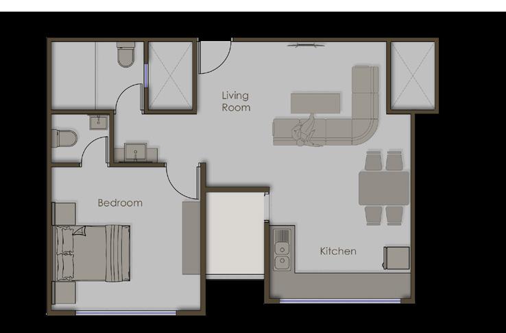
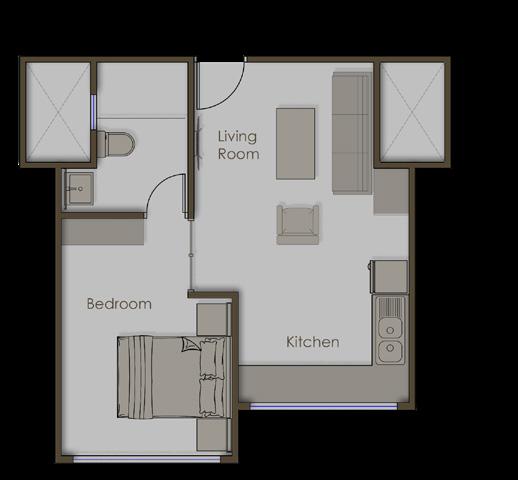
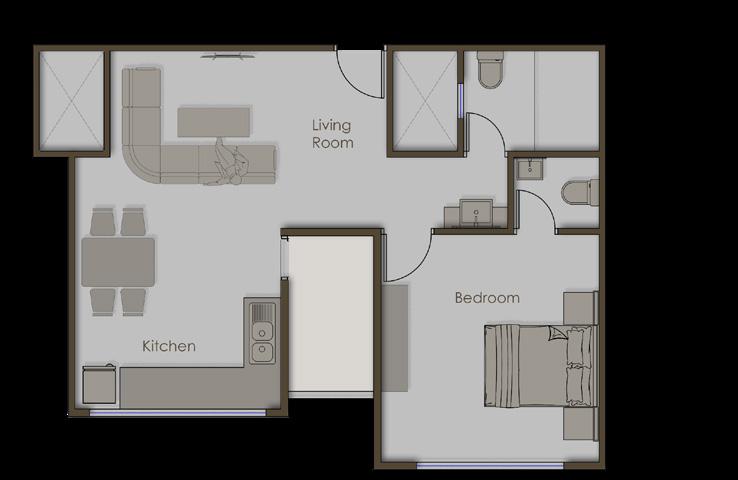


Studio Appartments
Room Appartments
Room Appartments
Room Appartments
Room Appartments 36 sqm per unit 54 sqm per unit 72 sqm per unit 90 sqm per unit 175 sqm per unit
2
3
5
4
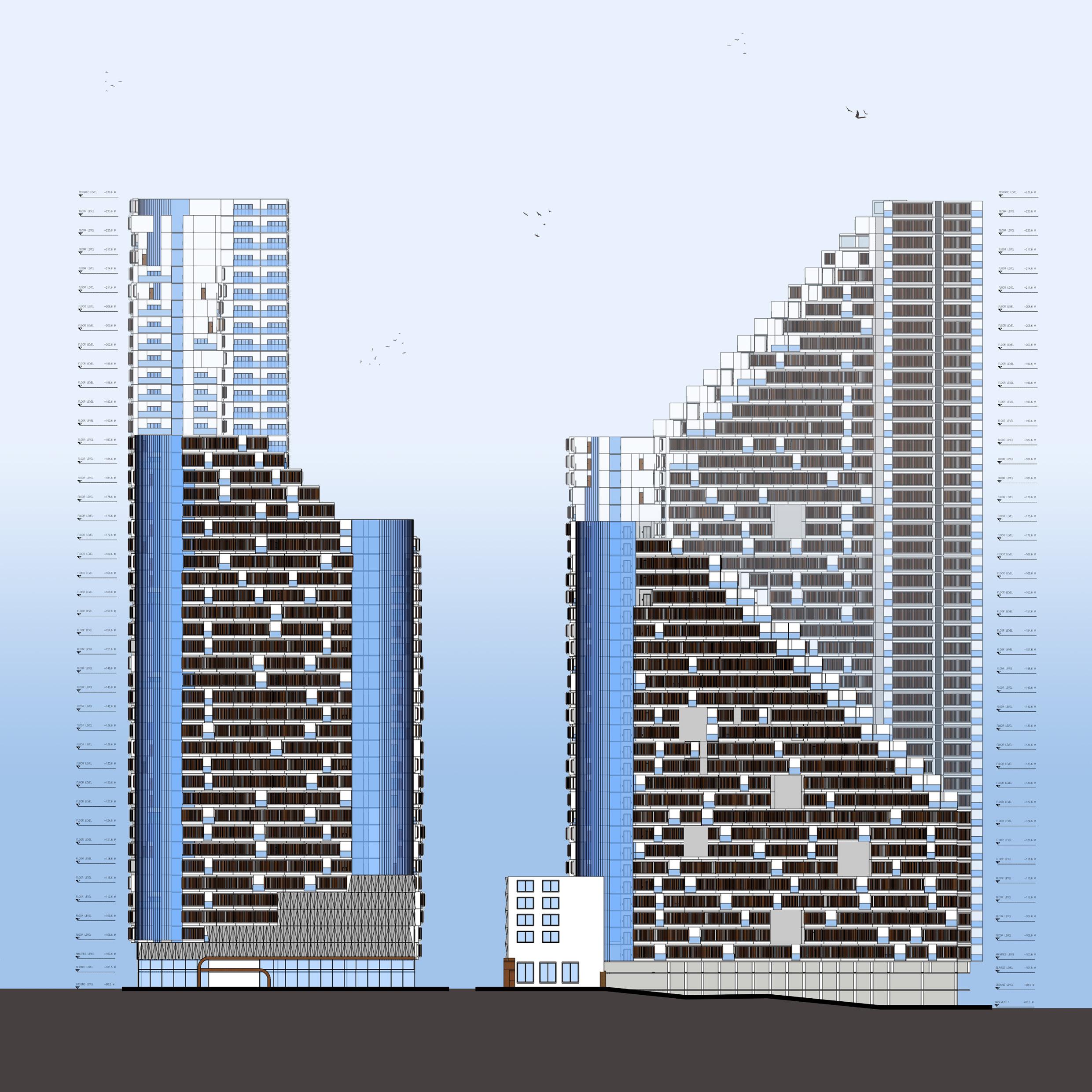
East Elevation South Elevation Road Facing Elevation Ramp Towards Basements
3 Neoasis
Jamalpur, Ahemdabad Luxury 5 Star Hotel
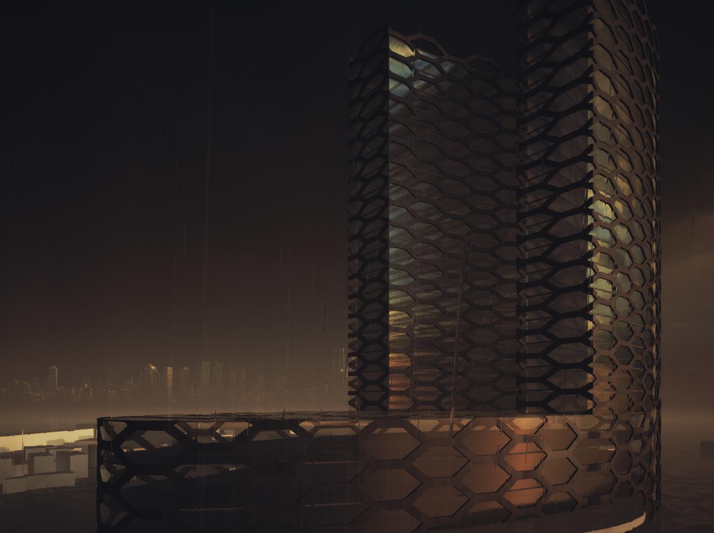
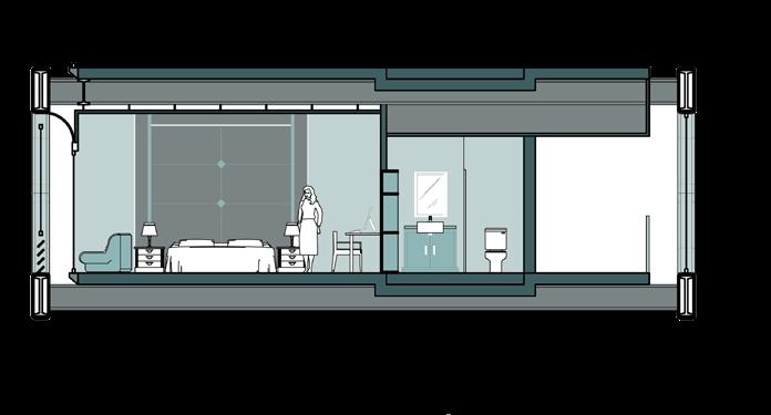
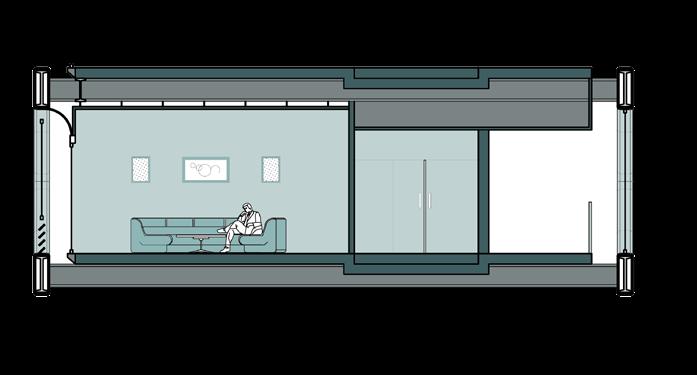
This 150-room hotel in Ahmedabad reflects the city’s rich culture and vibrant urban setting. Nestled between the Sabarmati Riverfront and the Atal Bridge, the design features stunning river views while utilizing new exoskeleton technology. This blend of history and modernity offers a one-of-a-kind hospitality experience, allowing visitors to immerse themselves in Ahmedabad’s colorful legacy while enjoying contemporary luxury.

Site Context:
The Site is located near Mitramandal Chouk, Swargate. A small water cannal is located towards the north of the site and swargate flayover towards the east.
Orientation of the site is at at 5 degree angle to the north and is surrounded by Dense vegetation.
The upcoming swargate Metro station is located towards the north east of the site and residential area towards the south.
There is a HCMTR being proposed on the north side and the site comes under the TOD area.

Site Plan
view of Arrangement of Rooms Open-Air Rooftoop Restaurant Premium Suits Service Area Circulation Lobby (Singly Loaded) Premium Suits Deluxe Rooms Standard Rooms Standard Rooms Fire Core 2 Fire Core 1 Building Exoskeleton (Steel Structure) Building Exoskeleton (Steel Structure) North Light Facade Covering Podium Rooftop Pool Service Core Passenger Cores
Exploded
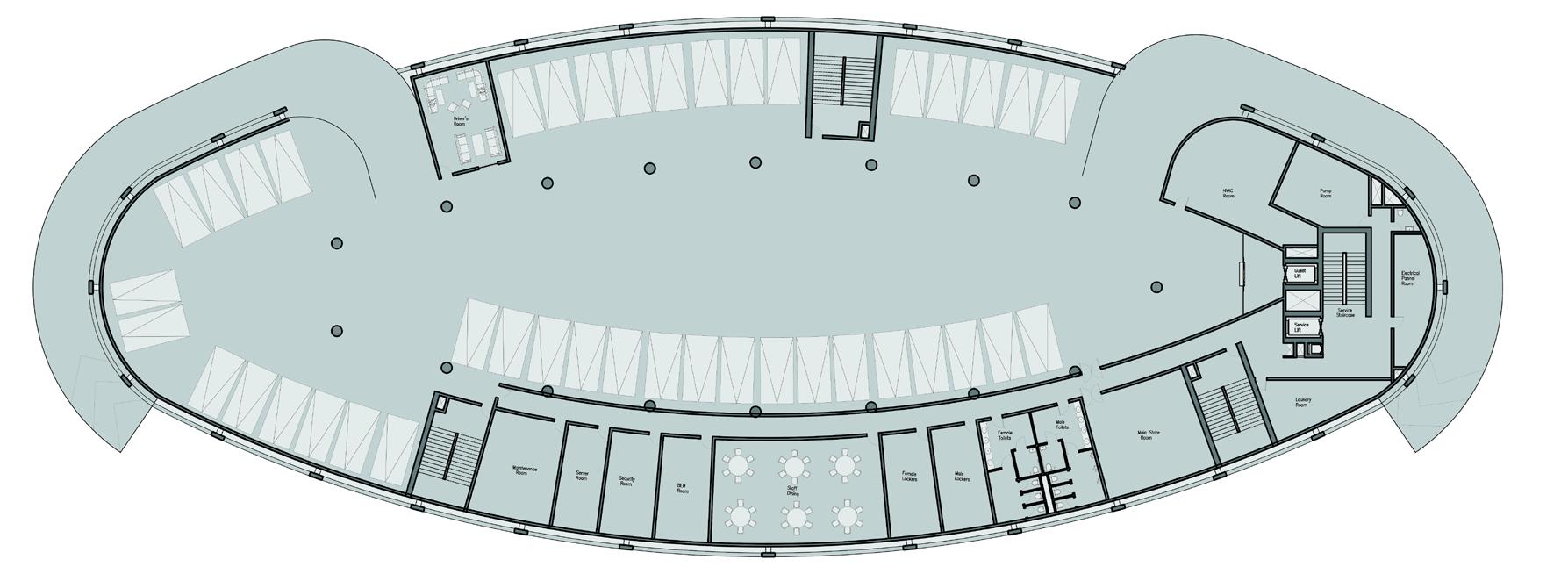
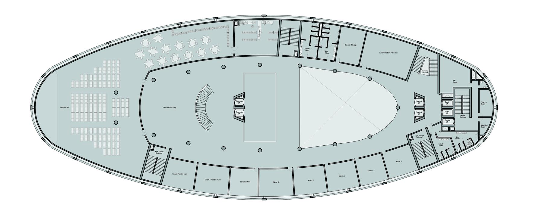
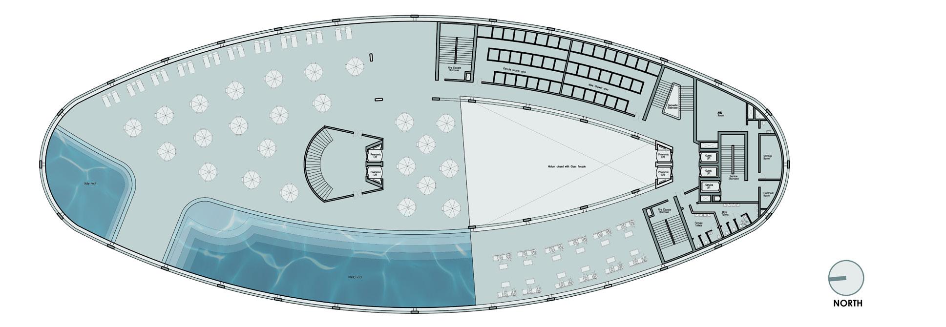
Podium Level Plan First Floor Plan Basement Level Plan
Isometric
North Light Facade Covering Building Exoskeleton (Steel Structure) Vehicular Dropoff Basement 1 Basement 2 Basement 3
Cut Section of Hotel Building
Sabarmati River
Public Open Space Atrium
Sabarmati Riverfront
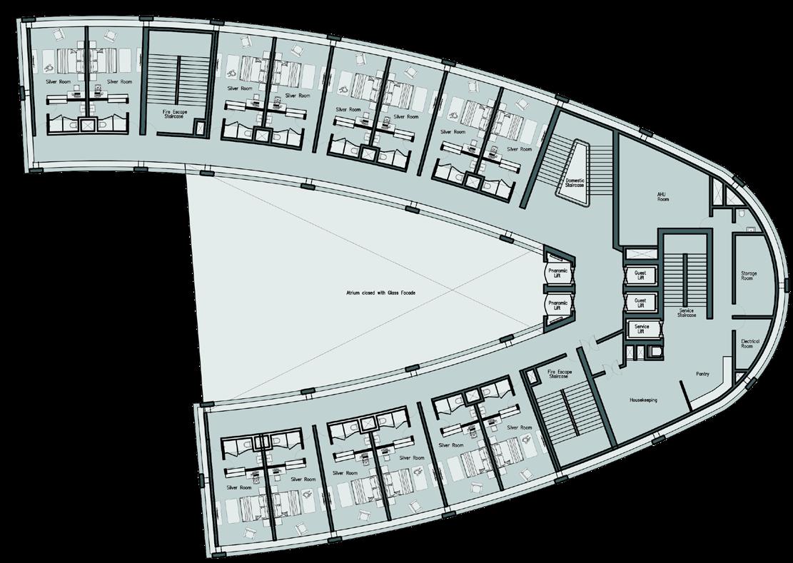
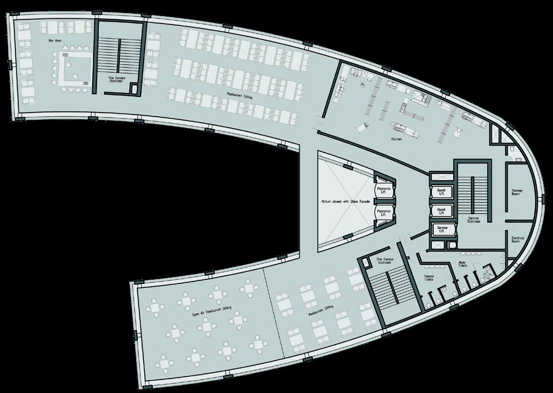
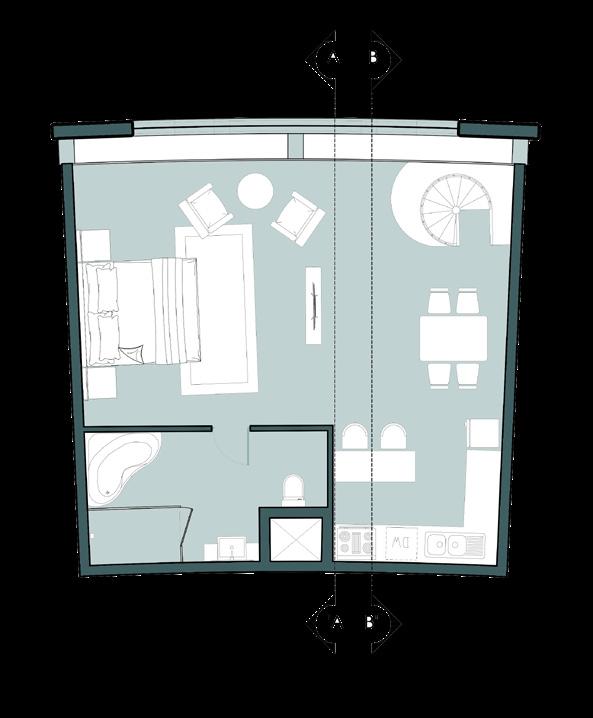
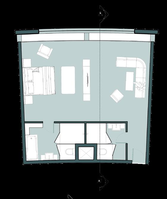
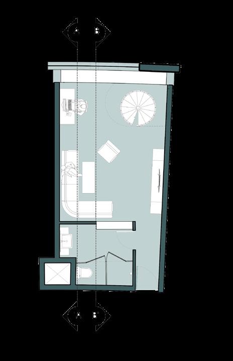
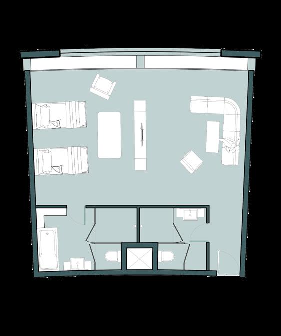

Floor Plan Rootop Restro Plan
Typical
Suits Upper lvl Plan
Suits lower lvl Plan
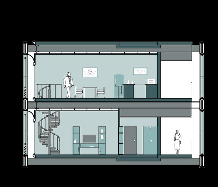
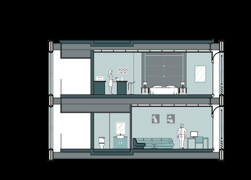
Section A-A'
Section B-B'
Delxe Room Plan A
Delxe Room Plan B
Standard Rooms
Delxe
RoomSection Standard Room Section
4 Queen Alia International Airport
Amman, Jordan
Long-span roof Redesigning
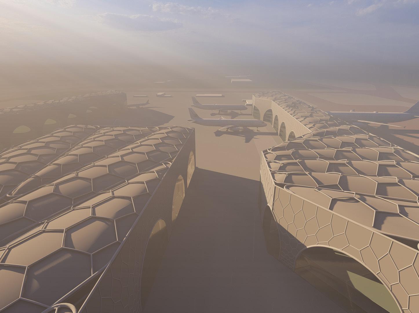
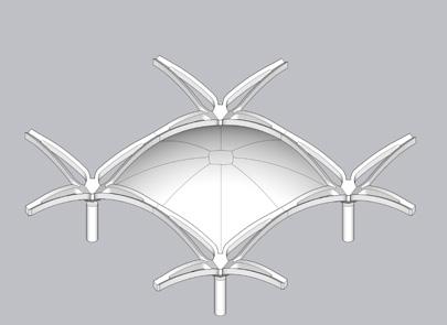
The roof and structural framework of Queen Alia International Airport were reimagined in this project. Departing from the original precast modular concrete domes, my design incorporates spaceframe and pneumatic roofing with Double layers to reduce heat input, solving a notable issue with the existing concrete roof. This modification improves functionality, sustainability, and passenger comfort. The project combines efficiency and environmental conscience, setting new benchmarks for airport design.
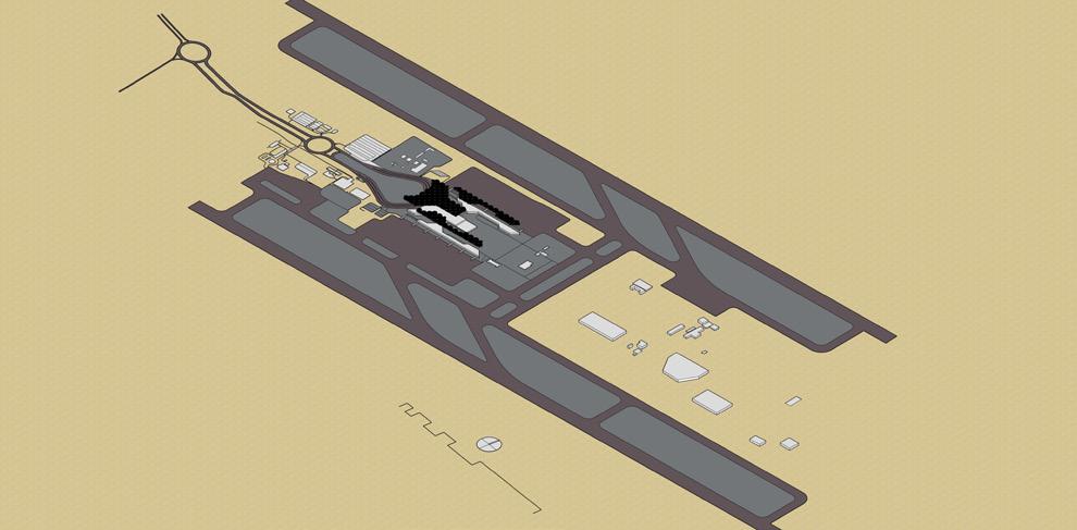

Site Context:
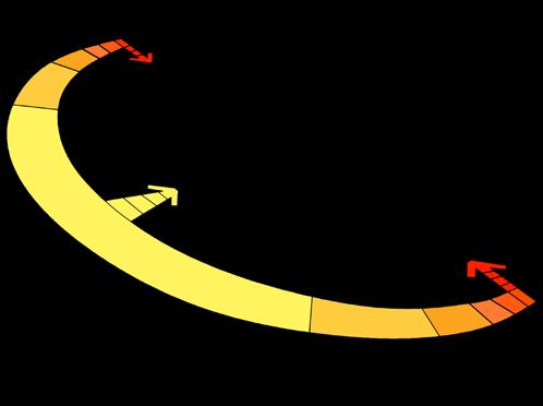
Jordan’s climate ranges between a more Mediterranean climate to a desert climate, but the land is generally very arid. Winter temperatures range between 19-22°C and Summer temperatures range between 3839°C. About 75%of precipitation falls during the winter.
The region is occasionally affected by hot, dry winds known as “Khamsin” or “Shamal.” The city faced a major earthquake in 1927. The overall loacation of the airport is remote, just connected via a major Highway.

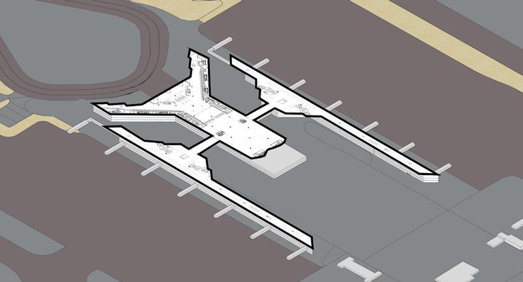
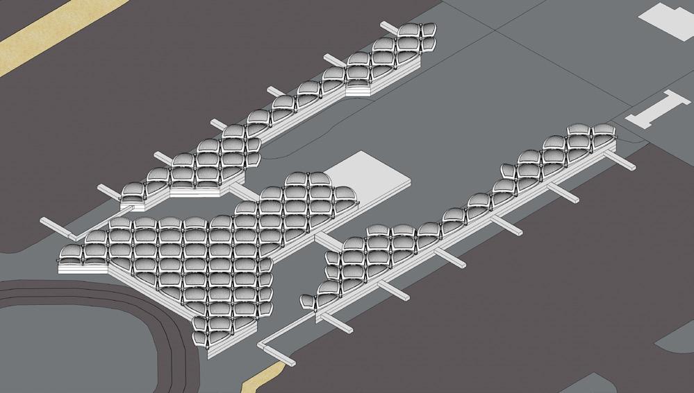
Floor layouts and Operations


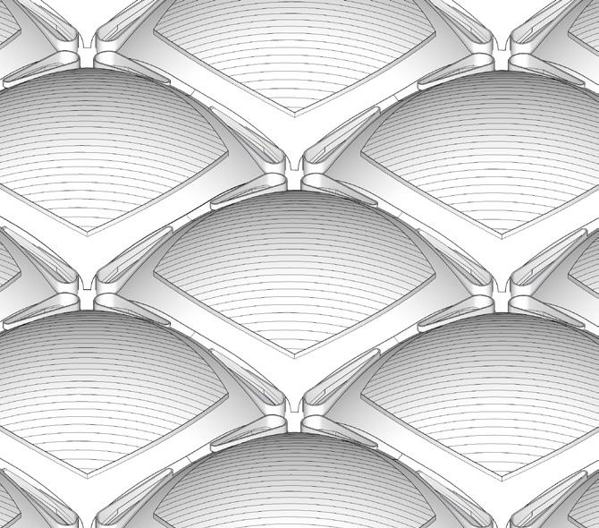
Existing Roof Structure Construction Process
Existing Roof Details :
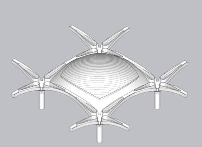
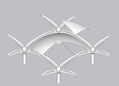
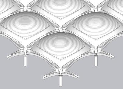
The existing roof was made using precast beams and domes, replicating floral patterns in nature. In the gaps between each dome, dropletshaped skylights allow light to filter through each space.
After the errection of columns precast beam formwork was used which was connected using 8 precast dome bases on which concrete was pored.More than 80 identical domes were made like a nod to the ancient desert tents in Jordan.
The complex geometry of the roof shells and fabrication strategy was developed by Foster + Partners in the year 1983.
Level 1 : Arrivals Level 2 : Immigration Level 3 : Departures
Step 1:
Step 2:
Step 3:
Step 4:
Step 5:
Step 6:
Step 7:
Step 8:
Long Span Roof:
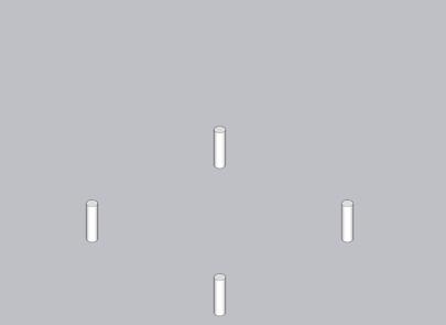
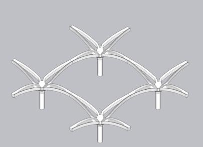
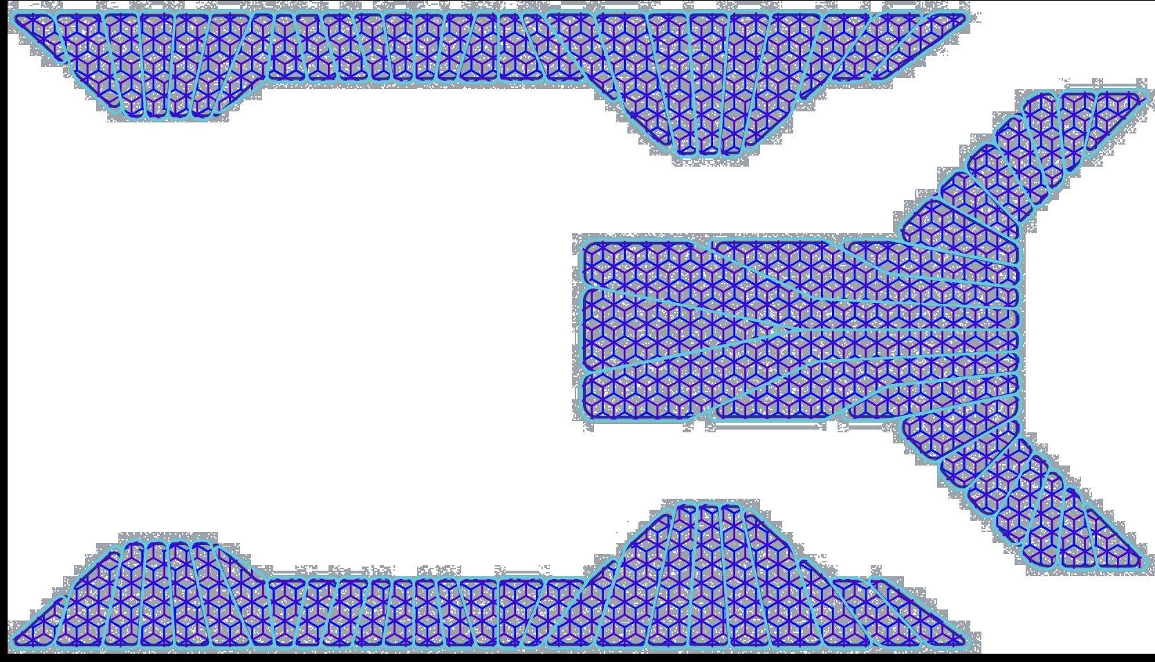
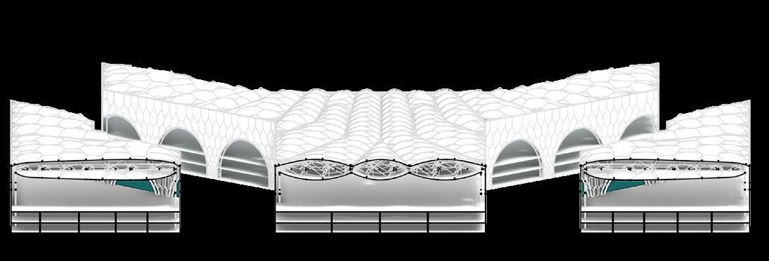
The Roofing is imagined as a singular structure and is designed by use of space frame Construction technique.
A hexagonal Grid of side 6m is used to hold this structure. 3 of such grids are implied on the roof at 3 levels and then connected via vertical connections. The overall load of this stucture is then passed on to the stanchions through the arches into the foundation.
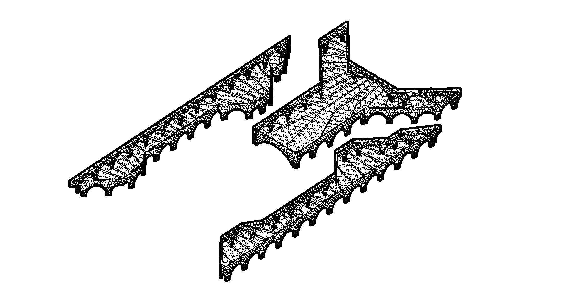
ETFE Roof Envalope
Glass Facade
Arched Facade
Perimeter Member
Hexagonal Space frame members
Spaceframe Members
Compound Stanchions
Structural System
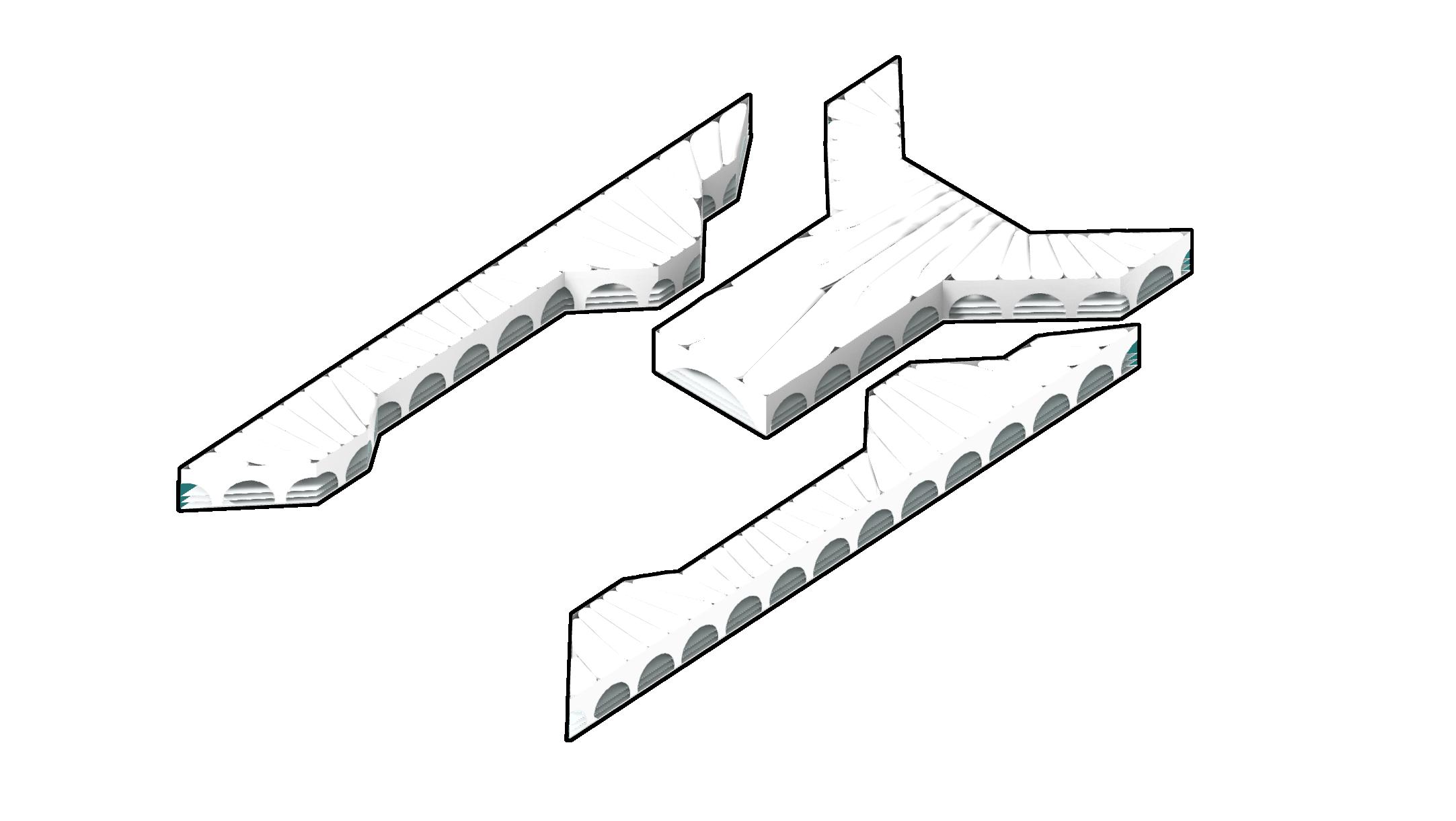
Inflated Roof with 2 surfaces
Pod Perimeter Members
Roofing system
Doubly layered Roof:
The roof is designed such that it can Sustain the inetnal temperature of Building. Internal temperatures of upto 5-6 o cooler is achived by having double layered ETFE roof which allows light inside without transmiting the heat.
A air pocket is created where the air is changed once every hour acting as a buffer between the insides and outsides.
Existing Floor Slabs
(Pod)

 Cut Section A-A’
Cut Section B-B’
Structural Roof Plan A’ B’ C’ C A B Perimeter Members Hexagonal Space frame members Pod Perimeter Members Vertical connections 448 m 33.5 m 33.5 m 86 m 228 m
Cut Section B-B’
5 The Twist
Palm Jumeirah, Dubai Highrise Steel Structure
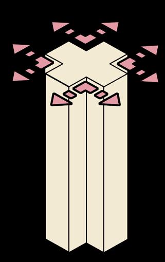
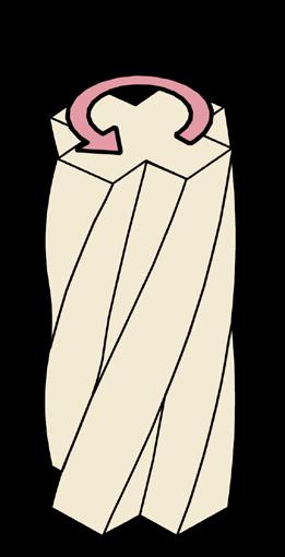
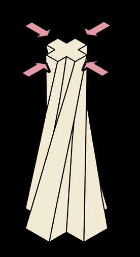
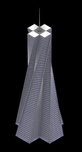
The design of this skyscraper on Palm Jumeirah Island is influenced by wind dynamics, and its unusual twist demonstrates both form and functionality. To provide structural integrity and stability, the design includes an outrigger truss system as well as perimeter mega-columns. This creative method not only respects the building’s particular setting, but it also establishes new standards for architectural stability and beauty. The a project that blends engineering and elegance, redefining skyline beauty.

Form Development


Aerodynamics:
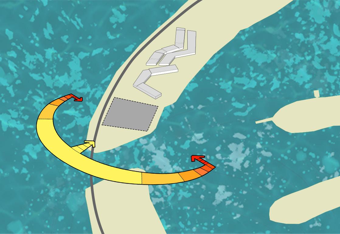
The Wind direction for the site is from North-West to South-East. Average wind Speeds are 357 cm/ sec (8 m/hr).
The Tower experiences the following effects due to wind:
A. Downdrafts-
The winds from the North-east when collides on the building and move downwards creating a strong wind upto 619 cm/sec towards the bottom of the tower.
B. Eddy Currents-
The wind that passes from the side of the building creates eddy currents towards the side of the building, which creates high
Site Context:
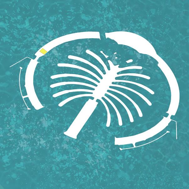
The site is located on the Palm islands in Dubai. This is a Manmade island constructed out of excavated rocks and sand.
The Site has a access through the major ring road which connects the outer islands of Palm Jumirah. The site is besides a luxary hotel towards the north.
Palm Island Construction:
These are one of the many artificial islands made by the UAE government to promote tourism.
The island was constructed through land reclamation, which involves dredging sand from the Persian and Arabian Gulf, spraying it, and “vibro-compacting” it into shape using GPS technology.
Foundations were created from 7 million tons of rock blasted from the nearby Hajar Mountains. The island also contains 120 million cubic meters of sand dredged from the bottom of the sea.
presssure zones (450-600 cm/sec) on sides and low pressure zones (0-200 cm/ sec) on the back side of the building.
C. Oscillation-
The tower sways due to the high and low pressure zones created on both sides of the building. To avoid this a Tuned mass Damper is installed at the 58 th Floor.

Mass Damper
45 th Floor 30 th Floor 15 th Floor West Elevation
619.28 550 500 450 400 350 300 250 200 150 100 50 0 Velocity Magnitude (cm/sec) 15 th 30 th 45 th
Tuned
maximize view
Plus
shaped Massing to
Twisting the top part 90o to Reduce Downdraft
Scaling the Top side to reduce dead load
Creating the structural system for the tower
Roof Slab
59 th Floor Slab
44 th Floor Slab
29 th Floor Slab
14 th Floor Slab
Ground Floor Slab
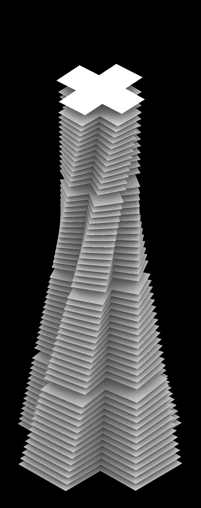
Floor Slabs
Floor slabs for each floor has a different shape due to the twisting nature of the tower. The 14th, 29th, 44th and 59th floor includes Mechanical floors and Structural Systems.
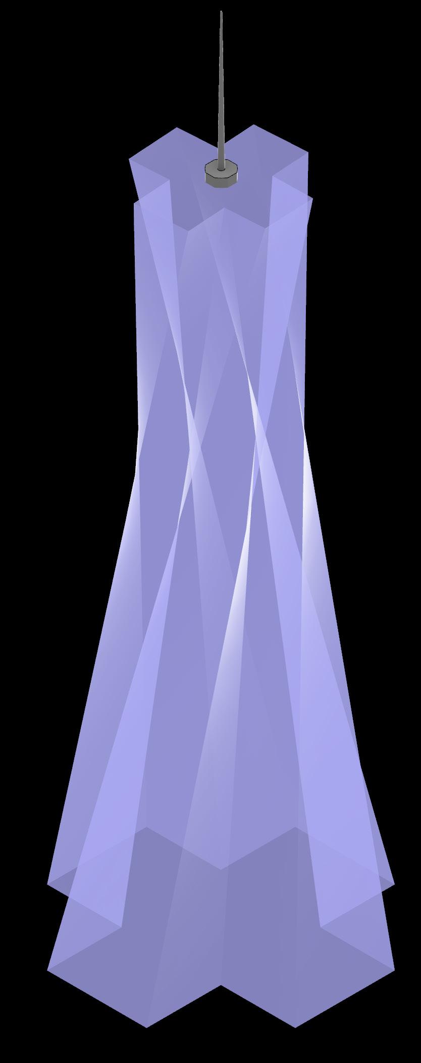
The Facade of the tower is done using Doubly glazed low-e glass with a U-value of 1.6 W/m2K to reduce the heat entering in the building. The size of the panel used is 2438 x 3500 mm.
Tower Massing and Core
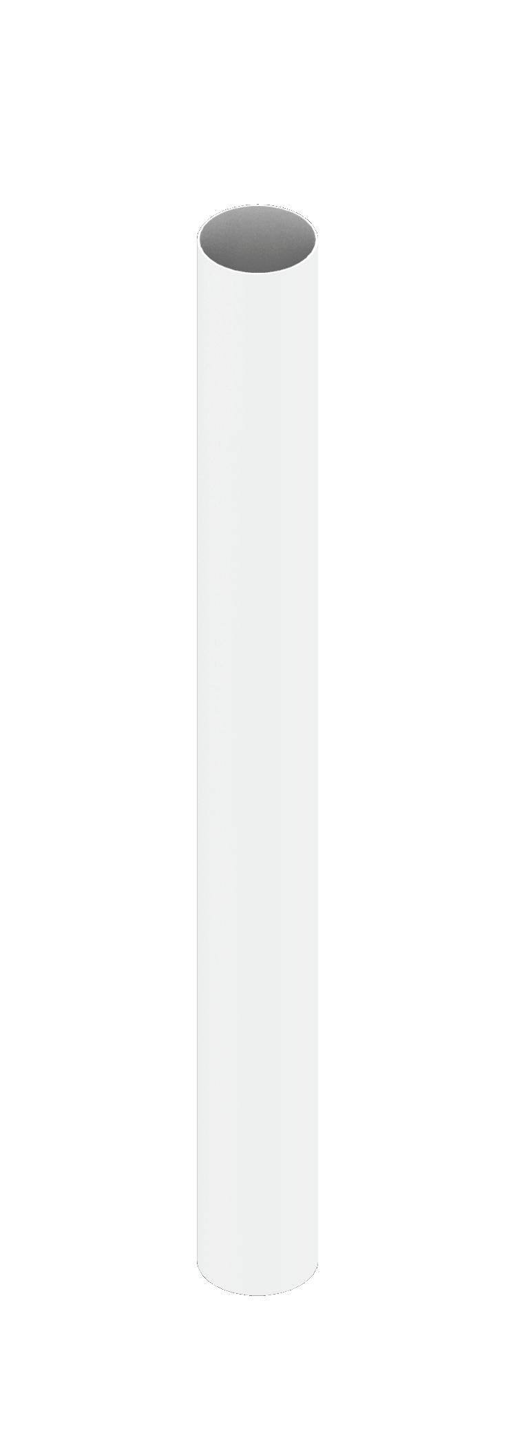
Glazing Core
450 mm shear wall Height 244m
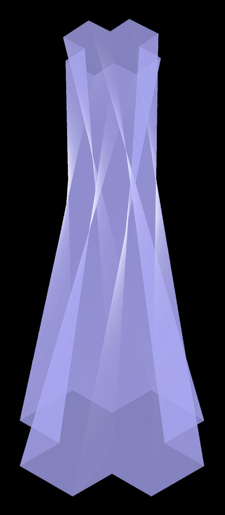
The building uses a circular core to acomodate the twist of the tower. The centrally located core has a Radius of 12m and includes 6 passanger lifts and 2 staircases. The walls of the core are made up of 450mm thick shear walls. Radius 12m
Lightning Arrester
Doubly Glazed low-e Glass

Belt truss
Outrigger truss

Belt truss
Outrigger truss
Belt truss
Outrigger truss
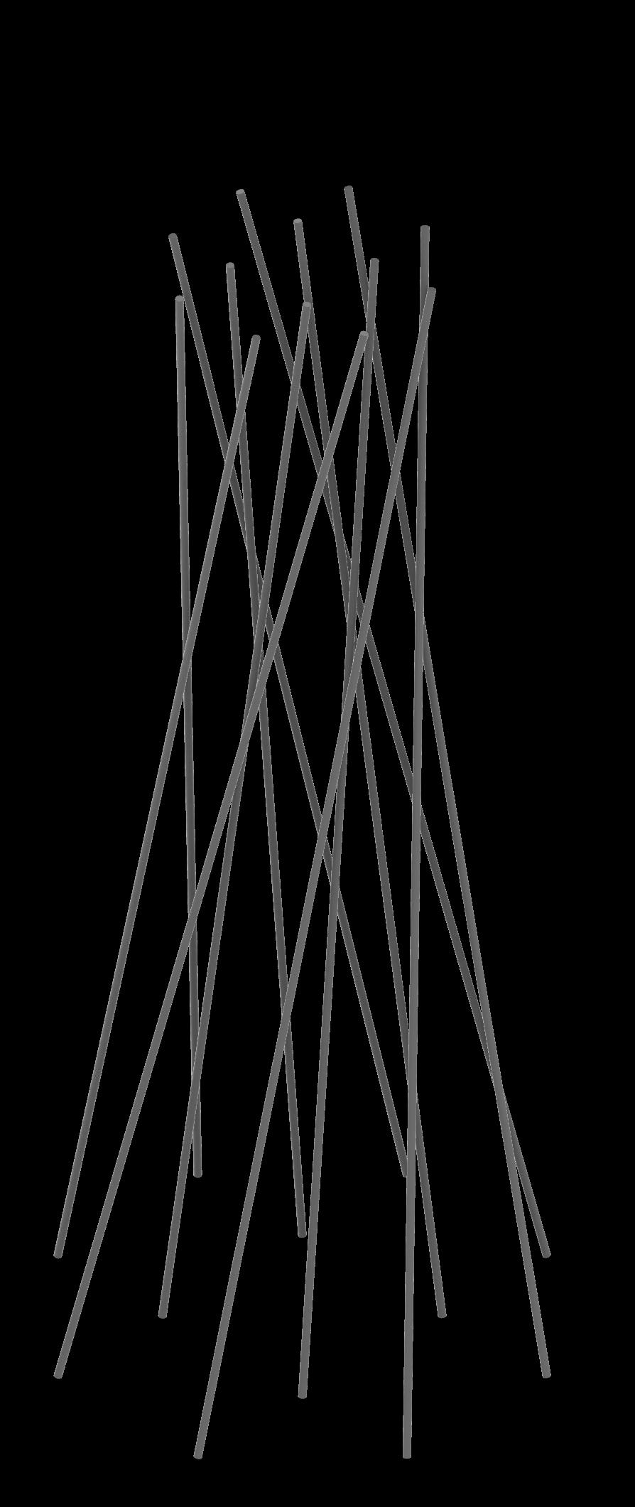

Outrigger Truss System Perimeter Mega Columns
To provide support from the Shear forces on the tower due to wind and Twist of the building, Outrigger truss and belt trusses are used. These are connecting the perimeter mega columns to the core to provide the necessary support to the structure.
To support the Vertical loads on the building, 12 mega columns are provided at the Perimeters with a diameter of 800mm at an angle of 1.5 degrees. Along with the vertical loads the columns also help with supporting the exterbal bracing system.
Structural System For the Tower

Cross Bracings
A system of cross Bracings is used to support the torsional forces on the tower. These bracings have a circular steel section with a dimeter of 300 mm and are connected via pin joints.
Belt truss Outrigger truss 1 2 3 4 5 6 7 8 9 10 11 12
14 th Floor Level 29 th Floor Level 44 th Floor Level 59 th Floor Level Perimeter Mega columns (800mm dia) External Cross Bracing (Circular hollow steel sections with 300mm dia)
6 Samuday Bhavan
Kudase, Konkan Community Empowerment Campus
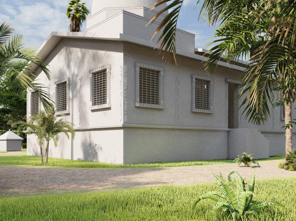
Kudase Village is one of the most picturesque places in Maharashtra, with strong social connections, but the village lacked a community center where people could gather. To address this issue, a community empowerment center was established, where individuals may receive basic education, employment for small businesses, and homestays for tourists.
Site Context:
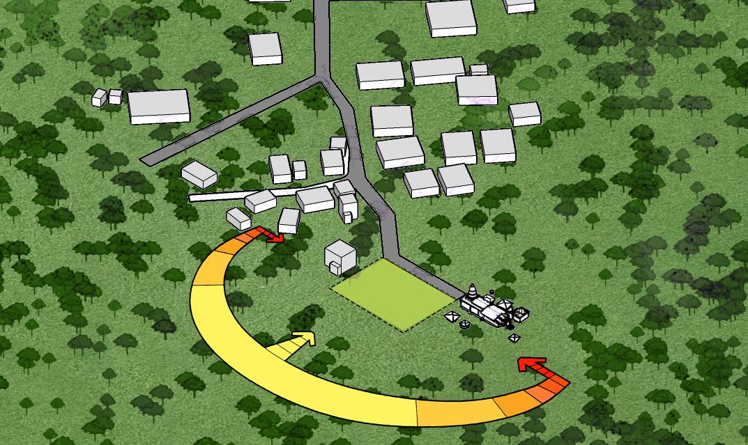
Kudase is a small village located in Konkan. The local cluster of the village has residences planned around a central branching road.
The site is near the Sateri Devi Temple complex. A 12m road connects the site to the village. On the south side there is dense vegetation and a river. The temple complex is surrounded by a forest area on 3 sides.

LEGEND:
1- Agro processing unit(cashew)
2-Anganwadi
3-Sadhekar house
4- Homestay
5- Library
6-Online study area
7- Community stage area
8- Community gatering and play area
9- Parking
10- Main vehicular acess road

Site Plan
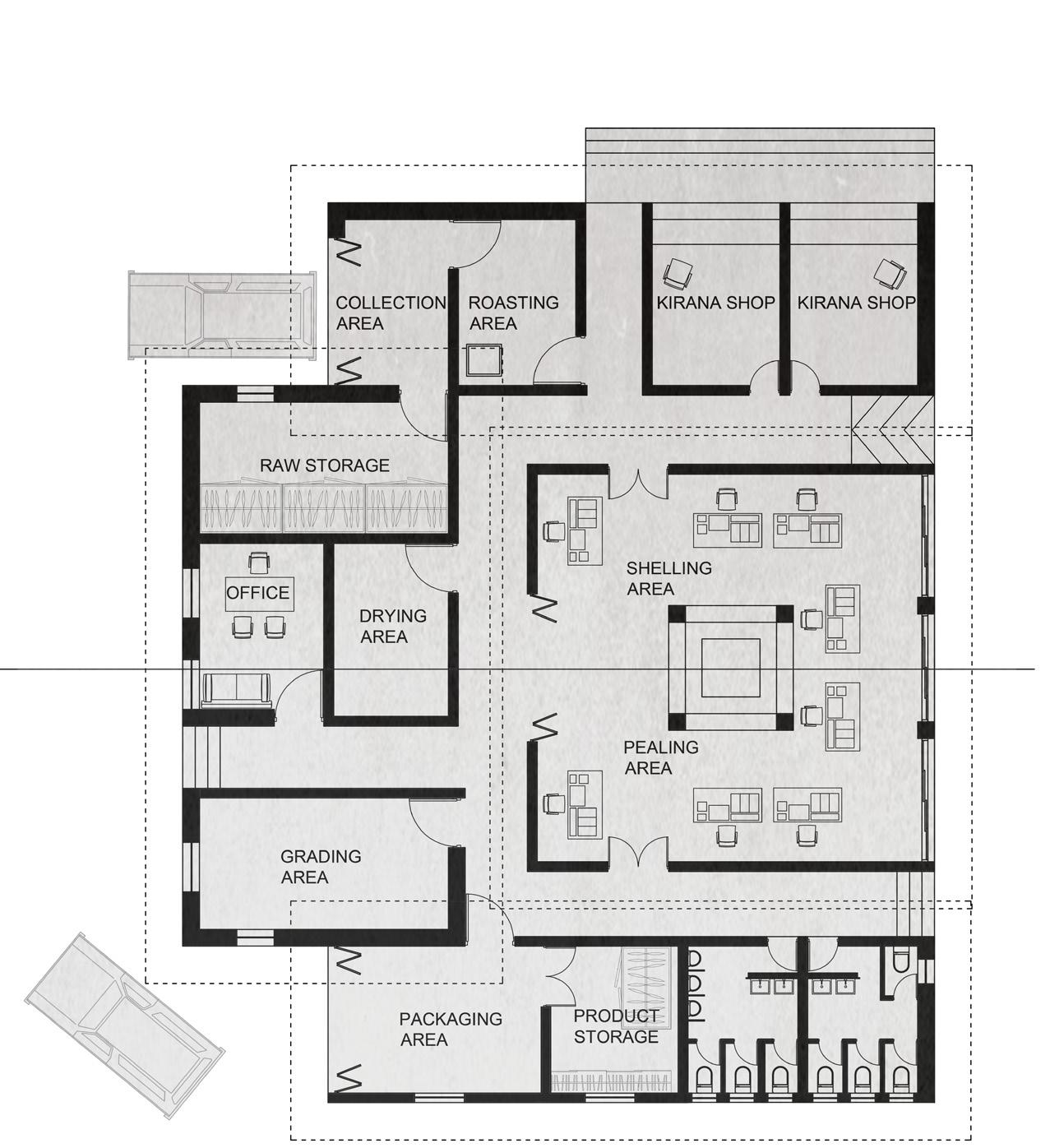
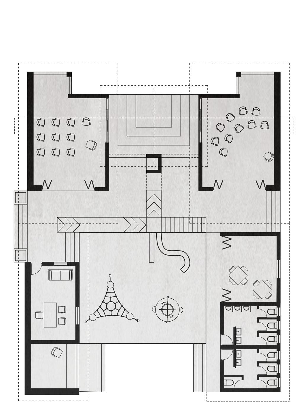
Plan of Anganwadi Plan of Agro Processing Plant
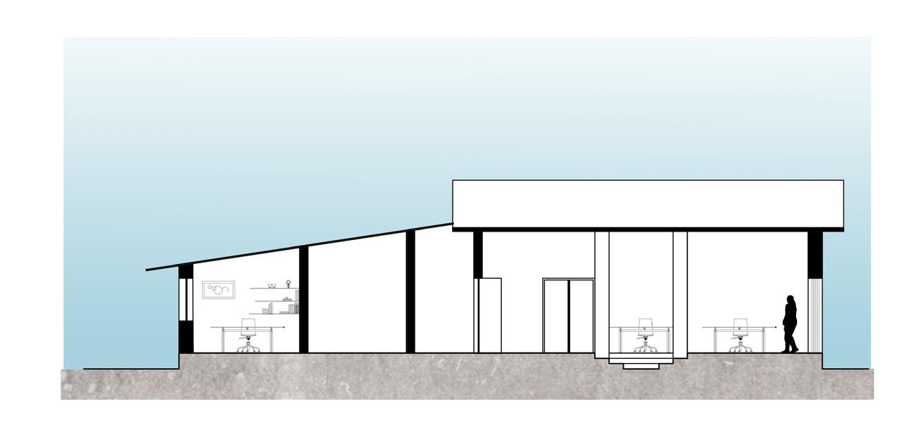
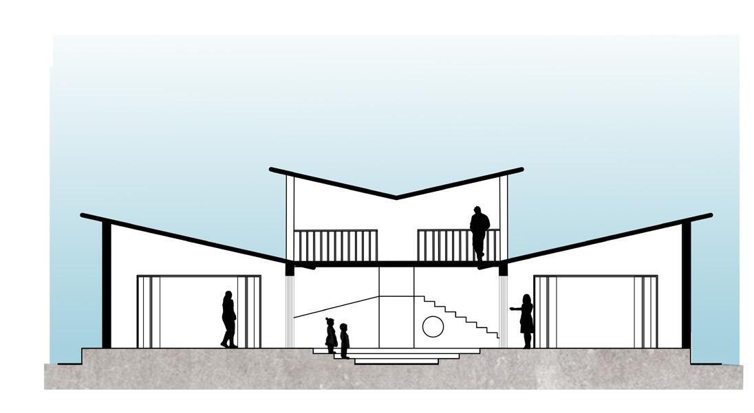
Section B-B'
A C' B' B
Section A-A'


Top of the wall
Top Plate
Lintel beam
Insulated windows Floor Finish level
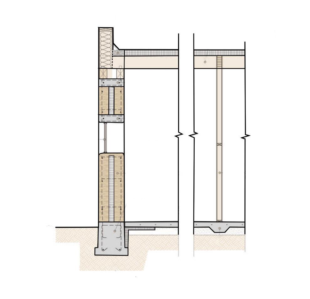
Footing RCC Bond Beam RCC Bond Beam 18' Thk Rammed earth wall Compacted Earth
RCC Footing
Detail for Rammed earth wall
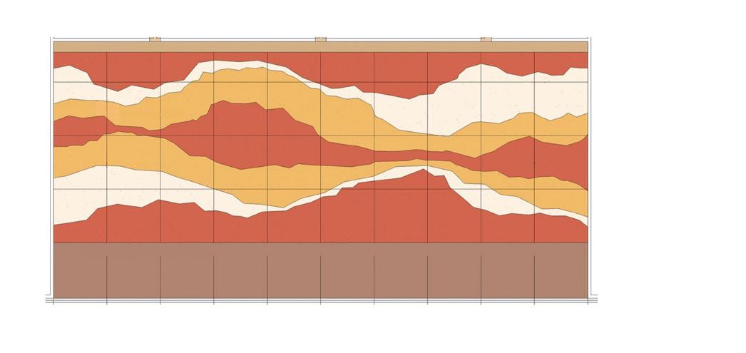
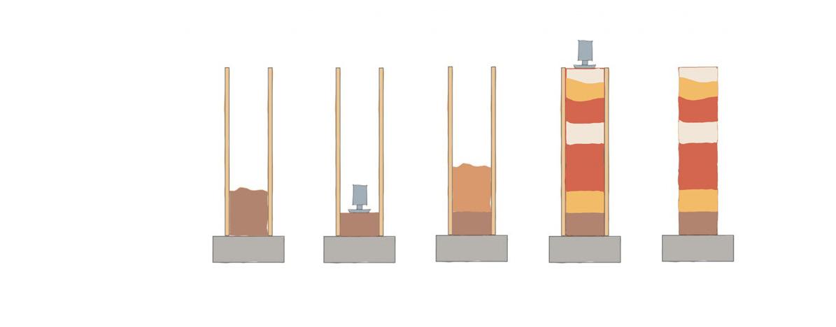
Rammed earth wall
Construction detail
Elevation of wall 5’ thick ply over insulation layer
2'x10' wood rafter @16'' c/c
2'x4' wood rafter @16'' c/c
Section A-A'
Section B-B'
Section C-C'
7 Lumos
Modular Facade Prototype
The project addressed the issue of glare in glass Facades in office buildings. This difficulty was handled by utilizing façade modules that moved kinetically in conjunction with light-based sensors. To let light inside, modules employed translucent fabrics. The design was created in such a way that the facade dynamics may be observed in various angles.
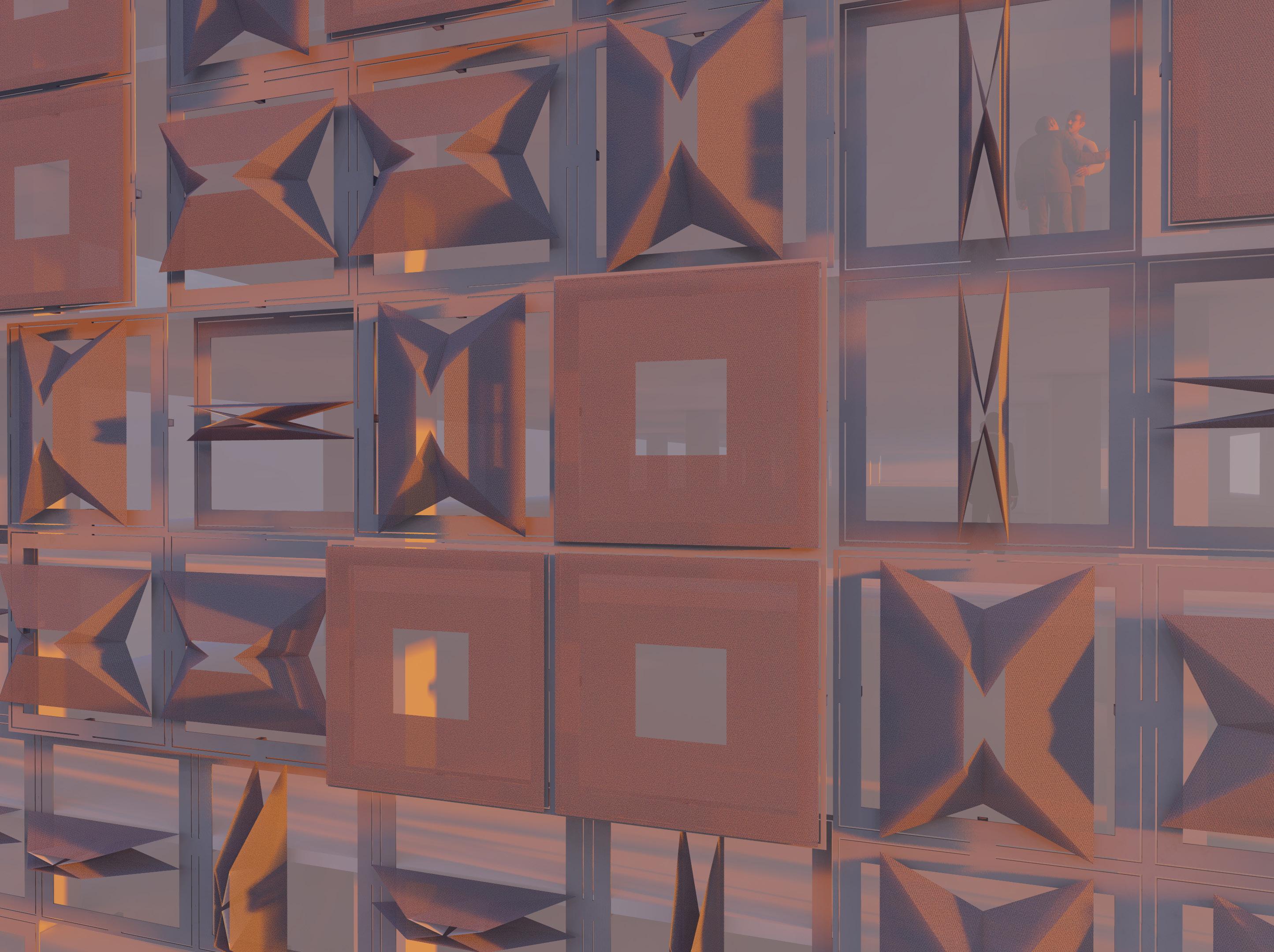
Ideation:
This module was created for Office buildings with Glass Facade. It can be used as a Vertival Shading device and Horizontal Shading device and also cuts glare in the closed position. It is divided into 4 parts with seperte module which act independently and can also form Parametric Design for Facade.
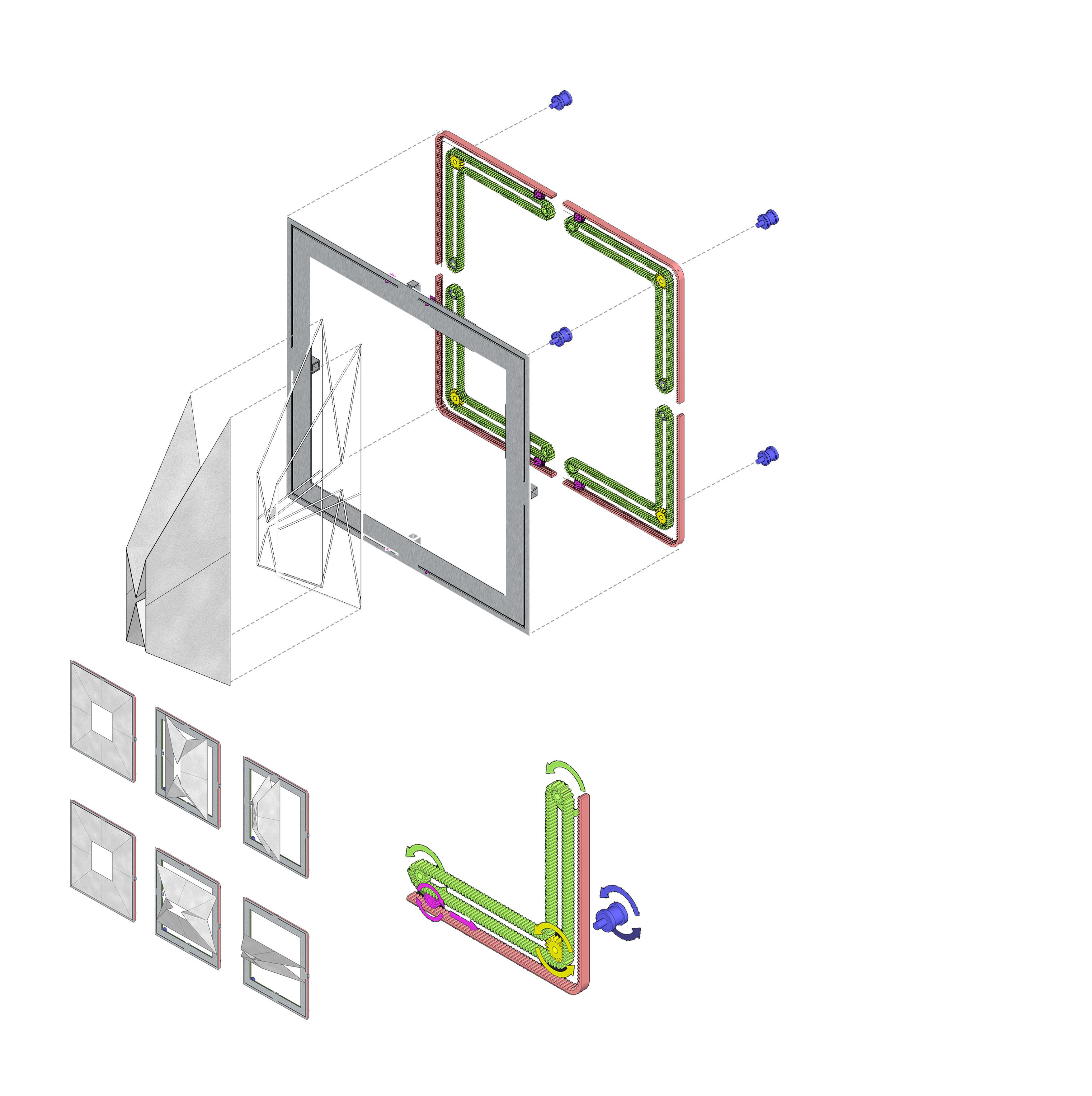
Module Detail:
Dimensions: 2400 mm X 2400 mm
Framing Material: Stainless SteelEnvelope
Material: ETFE Covering
Motor used: 240 volt Tubular Motors
Motor
Primary Gear
Gear Rack
Conveyor Gear
Secondary Gear Grove for tertiary Gear
Tertiary Gear (Connected to Envelope Frame)
Structural Frame
Envelope Frame
Envelope (Fabric) Module Exploded View
Working of gear system:
The Motor Rotates in Anticlockwise Direction.
The Primary Gear rotates along with motor in Anticlockwise Direction.
The Conveyor Belt is moved by the Primary Gear.
Conveyor Belt is assisted to move along L shape by use of Secondary Gears. The Conveyor Moves in positive direction, rotating the Tertiary gear in the opposite direction.
Due to the fixed position of the Gear rack, the Tertiary gear moves in Right direction to counteract forces.
As the Tertiary gear is connected to the framing of envelop, it moves it in right direction, closing the window covering.
Gear system for Module
1. 2. 3. 4. 5. 6. 7.
Different Module states
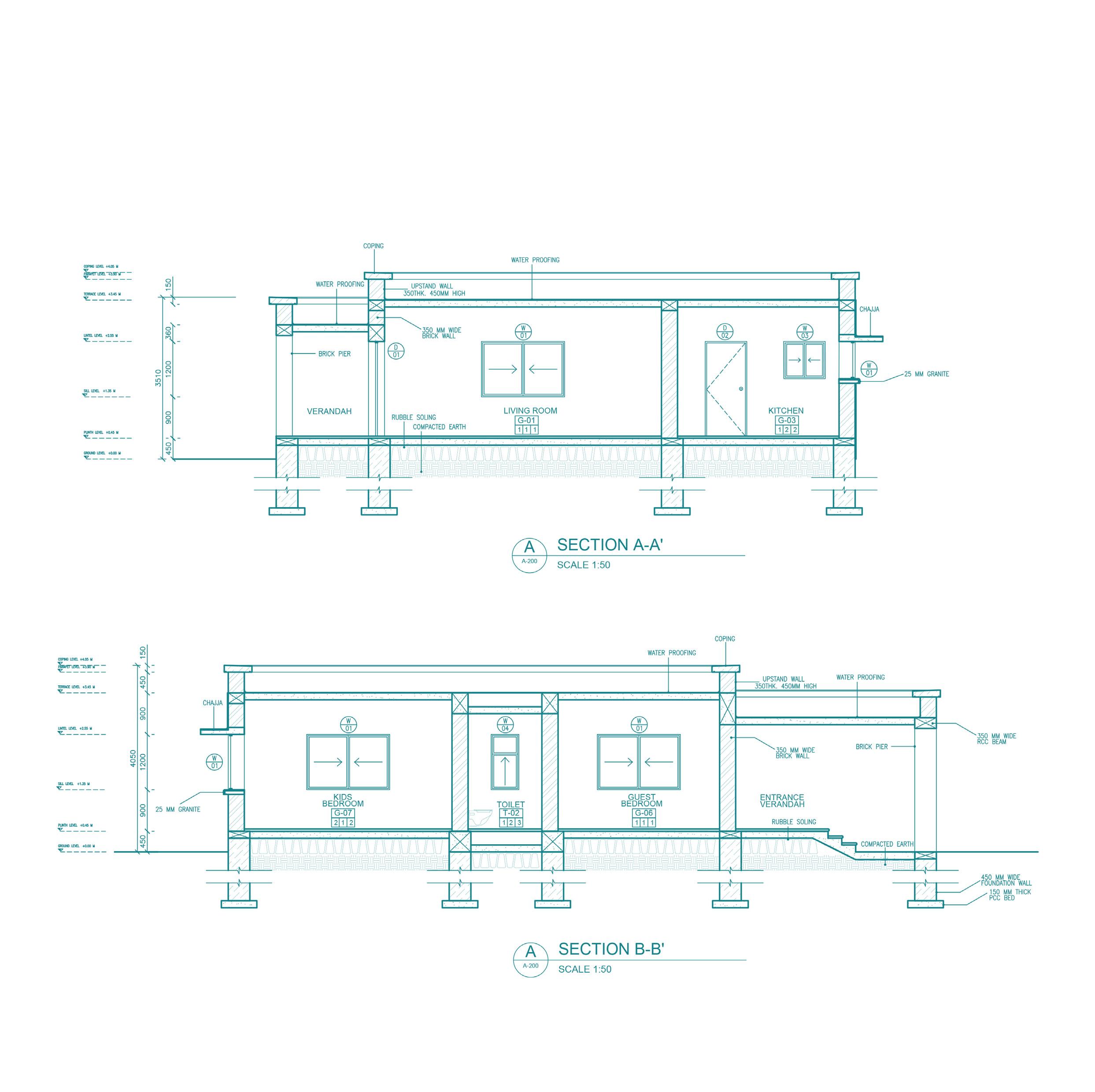
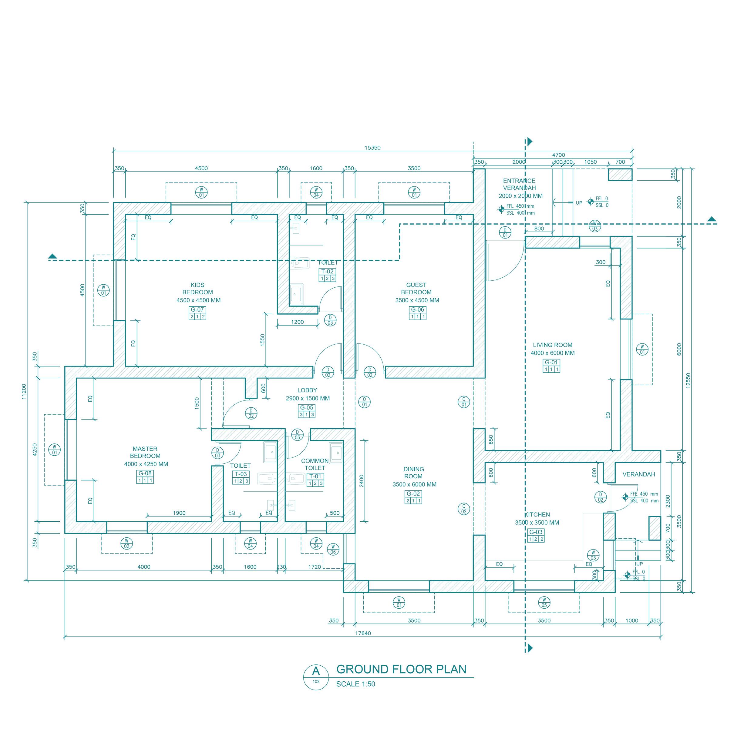
Working Drawings
A A' B' B

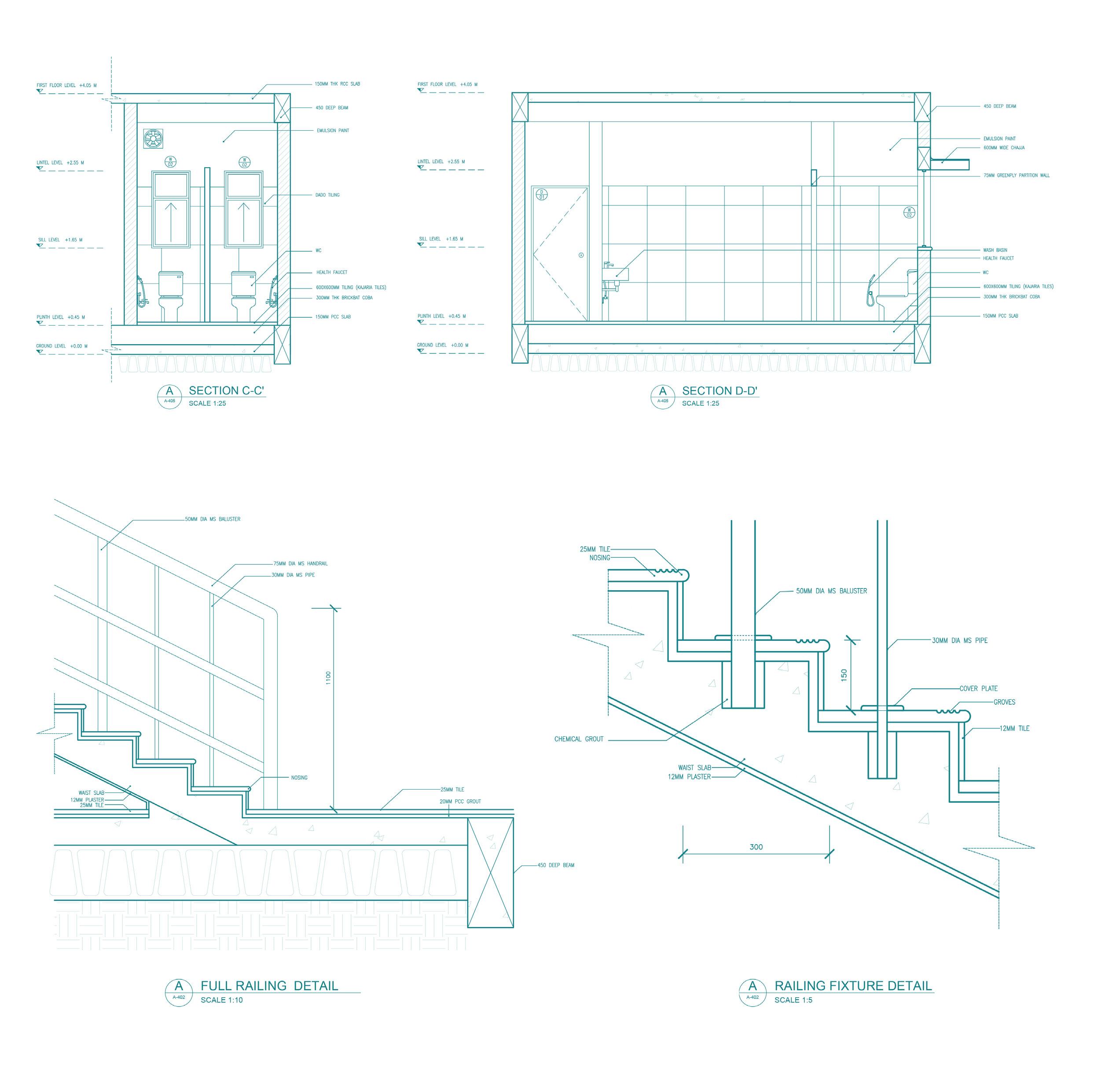
Technical Projects

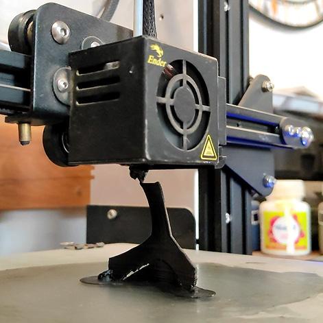
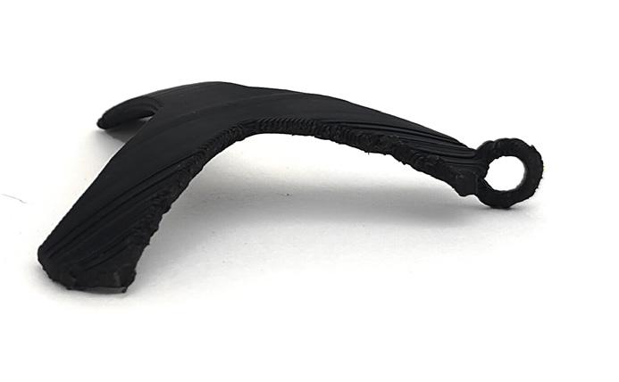
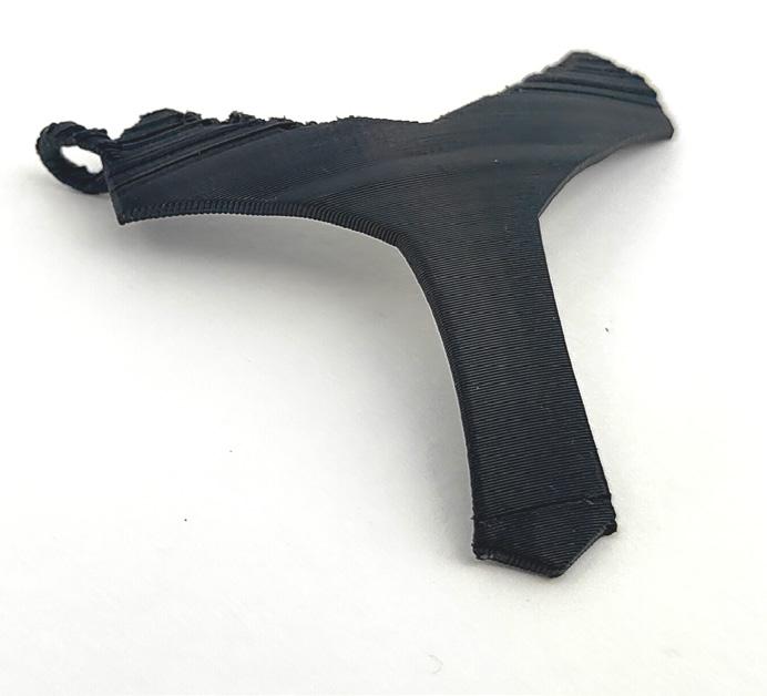
 3D
3D
Printing, Photogrametry, Lazer Cutting and Modeling Scripts
3D
Printing Ultimaker Cura, Ender Pro Printer
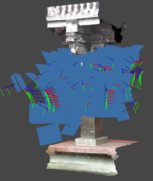
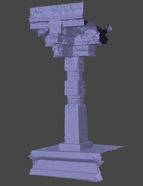
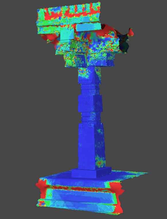


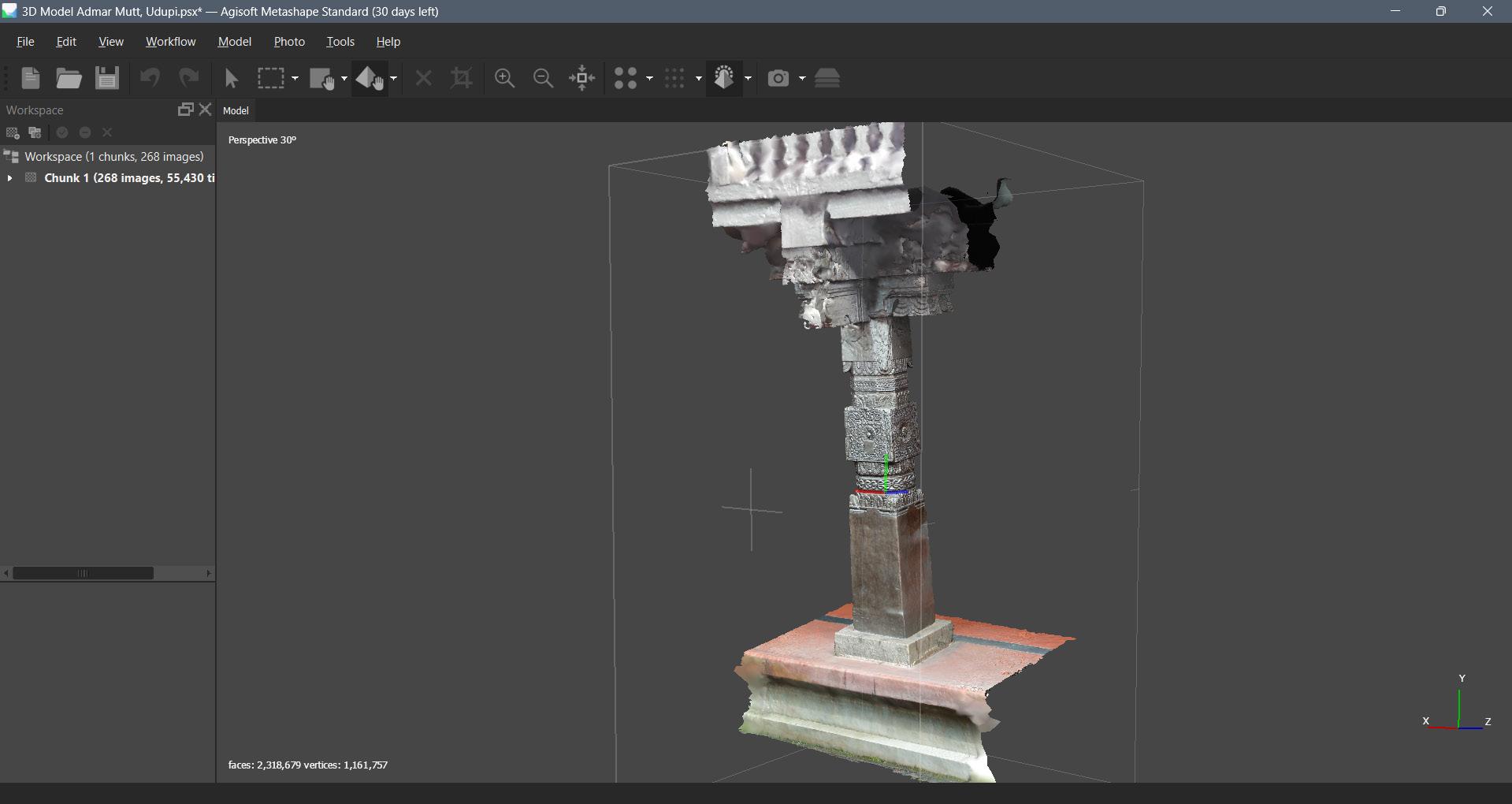
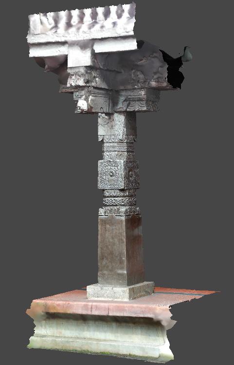
 Photo Alignment Mesh Model
Agisoft
Confidence Map Photogrammetry
Metaface
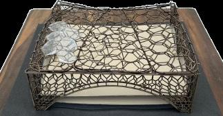
Lazer Cutting
Autocad, CNC machine
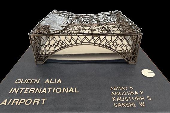

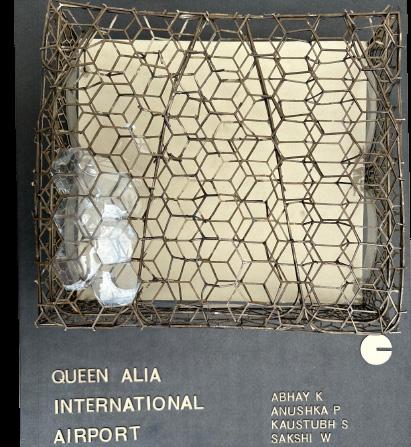
Modeling Scripts
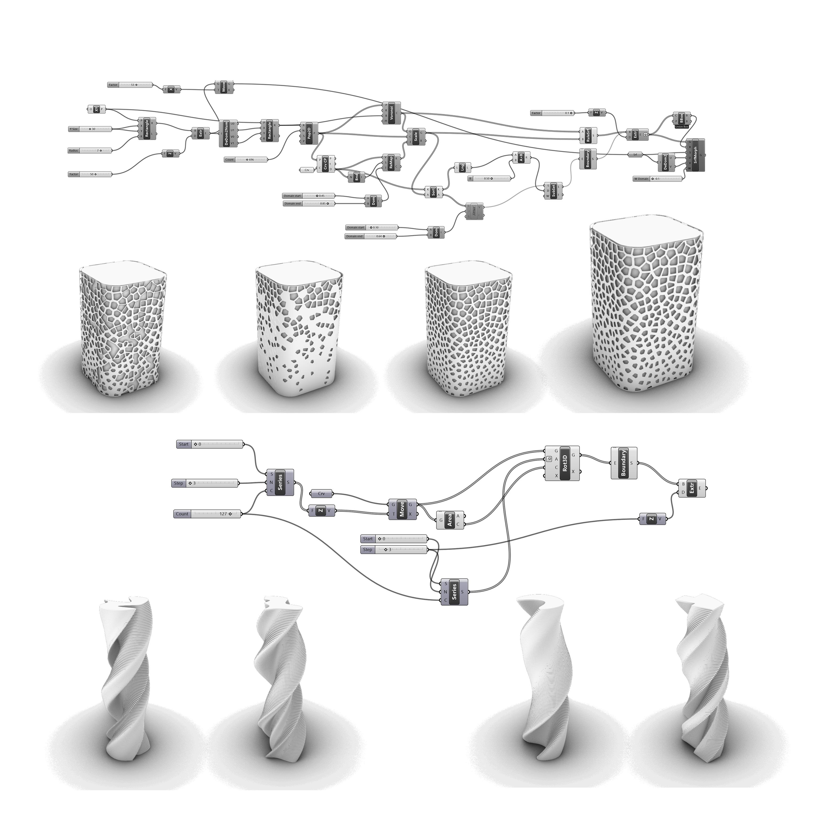
Rhino, Grasshopper
Voronoi Facade:
Twisting Tower:
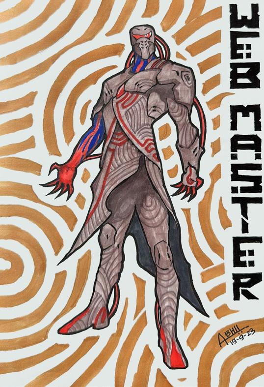
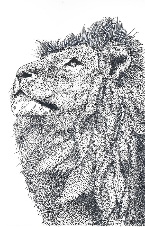
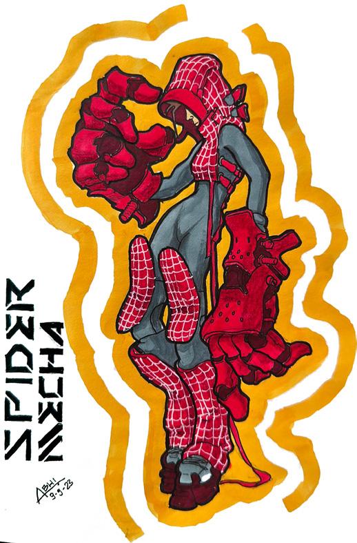
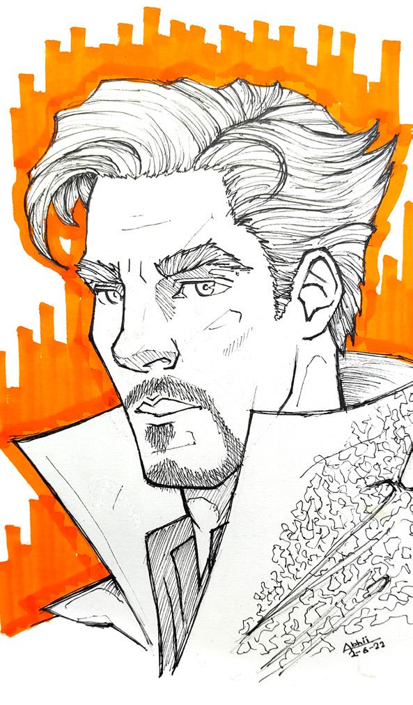
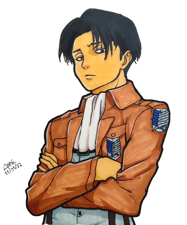
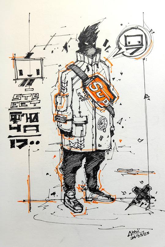
Artworks
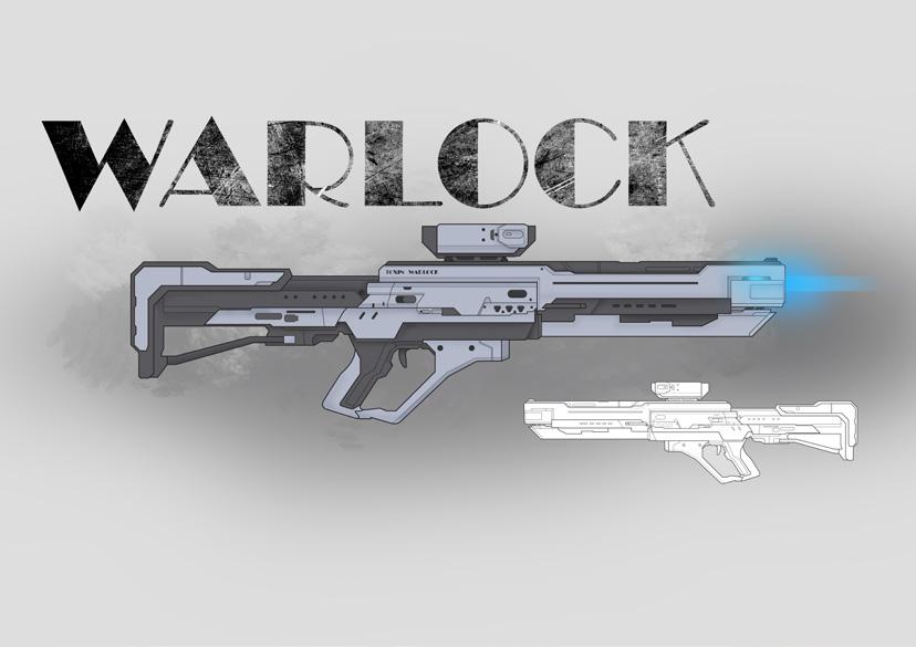
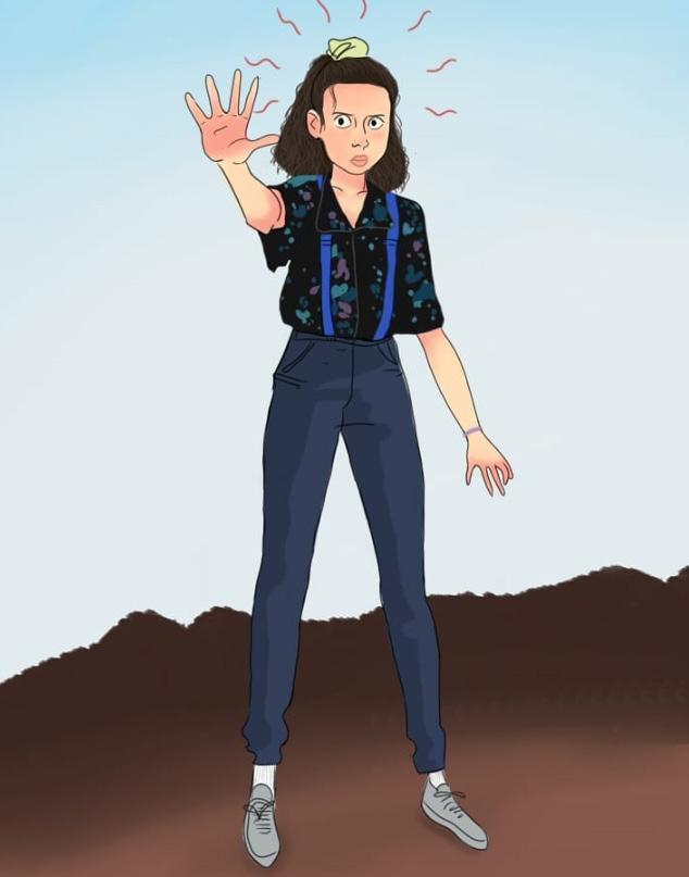

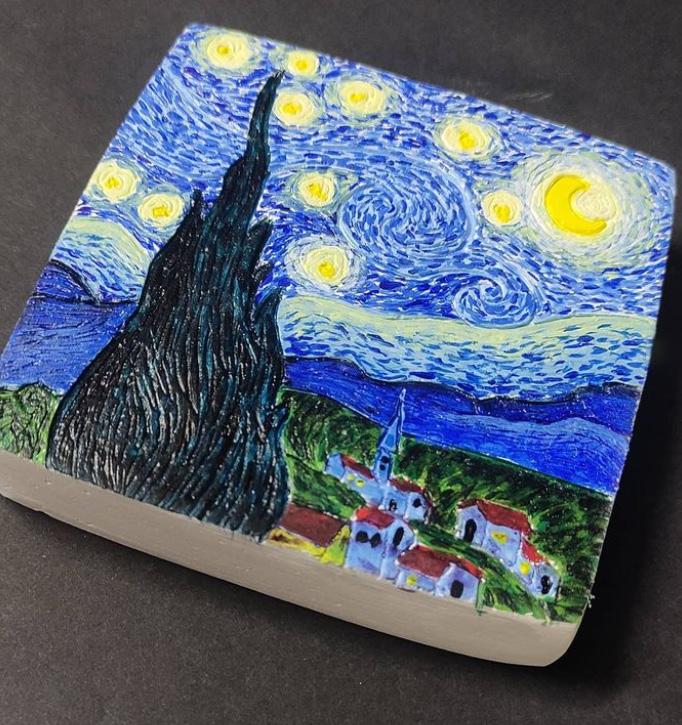
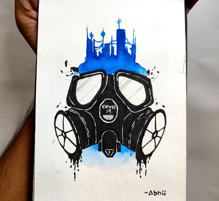
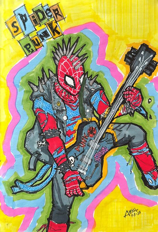


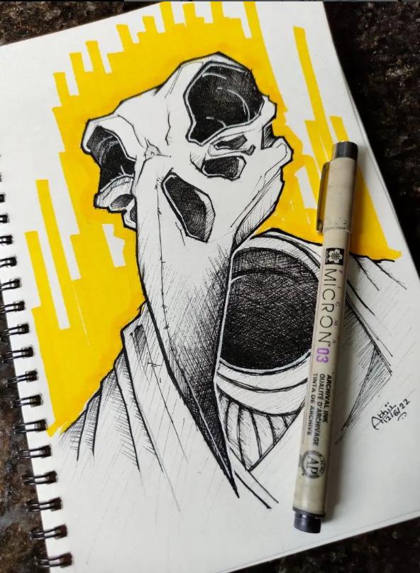



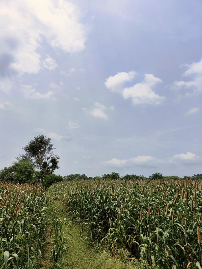
Photography







 Cut Section A-A’
Cut Section B-B’


 3D
3D


 Photo Alignment Mesh Model


