TOM SCOTT
UCL PORTFOLIO
ADAPTABLE PAVILION
Institution: Manchester
Year: 2022
Type: Pavilion
Research: Social Architecture in Latin America
Software: Rhino, Grasshopper, Blender
2 THOUGHT PATTERNS:
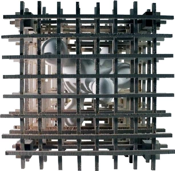
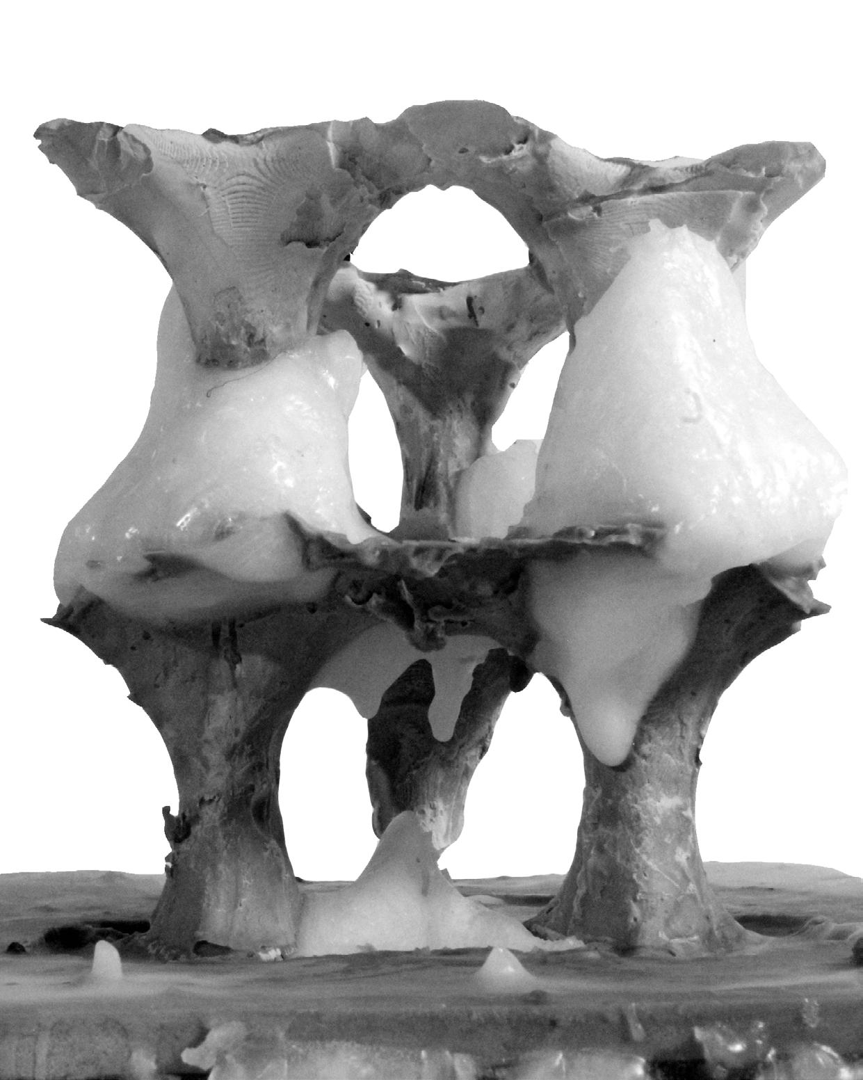
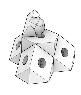
Exploration of material entropy: An imprint of wax casting onto concrete. Over time. as the wax would melt away, the concrete form is left behind; duality of individual material entropy.
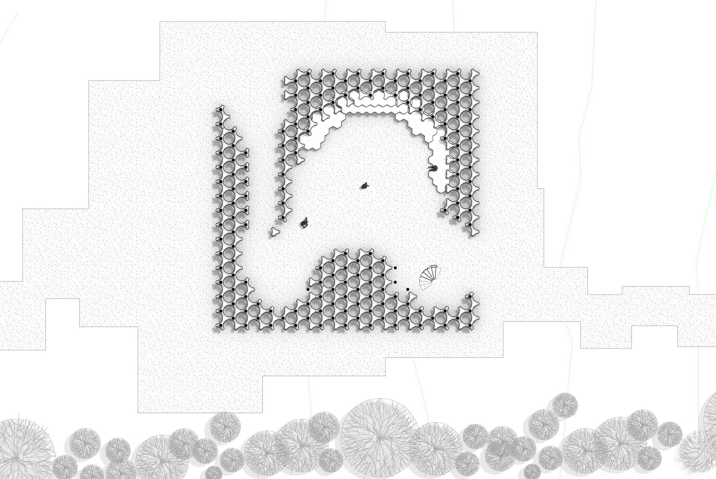
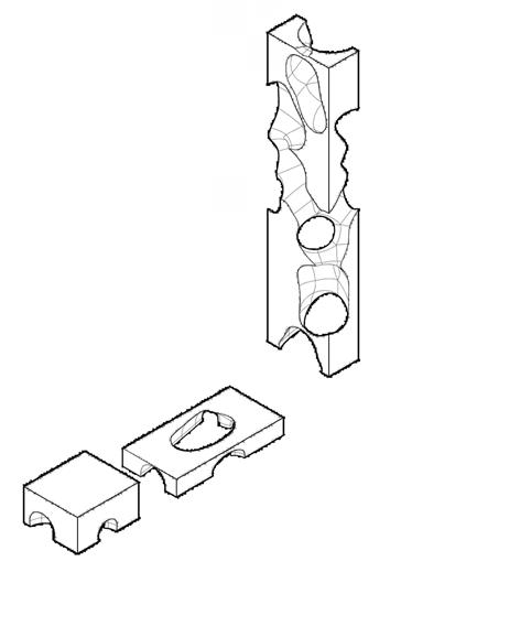
Adaptable grid: Under the inspiration of Matta Clark, decommodifcation of architecture, I aimed to include the public in constructing the space. A grid layout was set as the template, or background, which could be then subtracted in construction to form fluid spaces.
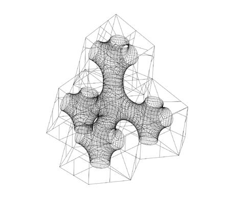
AJSubtraction of Form.
Fluidity of space represents adaptable and converging programmes.
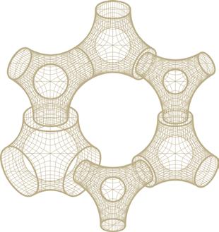
Subtracted form is reduced to a grid structure.
Grid Structure is broken into competent parts.
Structure can be remade around an adapting programme.
Fluidity is represented in grid components.
Tom Scott Portfolio 2
1 2 3 4 5 6 1 2 3
3 4 5 6
Scott Portfolio
Tom
Ground floor plan 10m
Digital Analogue
FABRICATION
5
Intermediate stage of structure through wax melting process
Structure post wax melting process
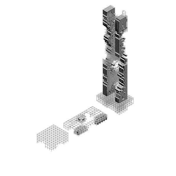
ADAPTABLE HIGH - RISE
Institution: Making
Year: 2022
Type: High-rise
Research: The work and radical visions of Cedric Price
Software: Rhino, Grasshopper, Vray
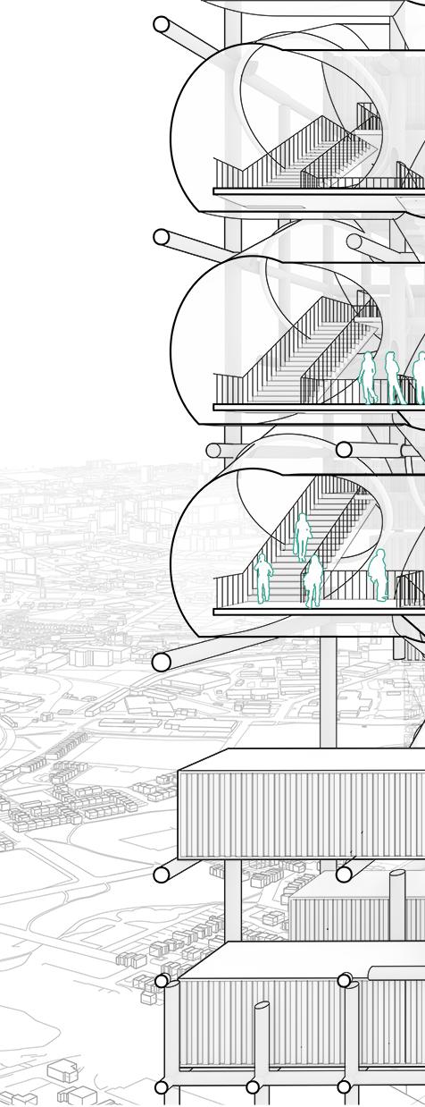
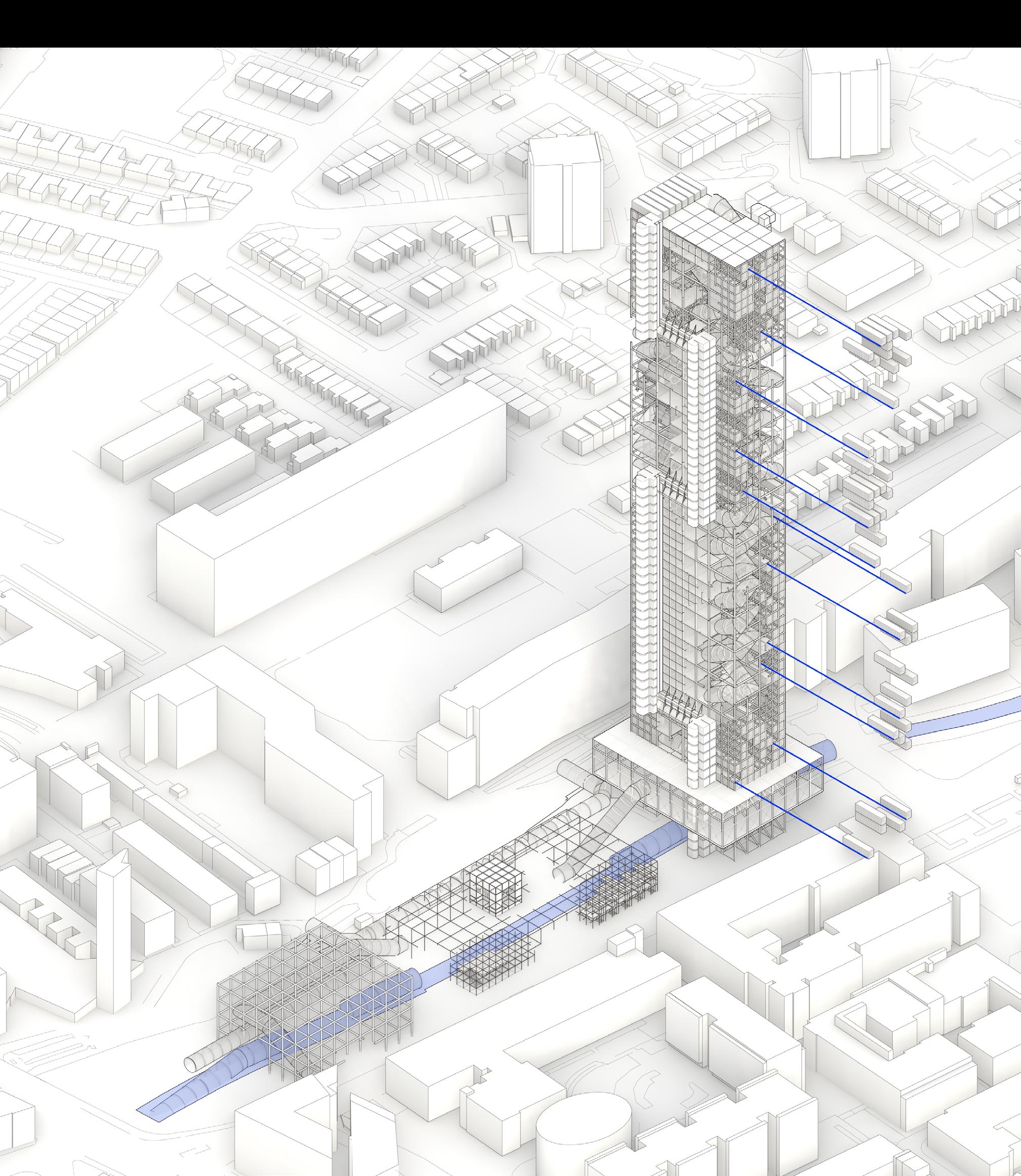
My work explores modular design, adaptability, and connectivity post covid. I aimed to change the workplace.
Occupants or office staff can subscribe to an allotted space within the building, followed by an installation of a modular private office reused from a container, or if teamwork is
needed, they can opt for an open suspended mezzanine.
All floors are connected via a public space tube lined with seating, incentivising cross department and multidisciplinary cultures.
I explore the work of Cedric Price, facilating agency in the community through commerce, and play.
Tom Scott Portfolio 6
1
AJ
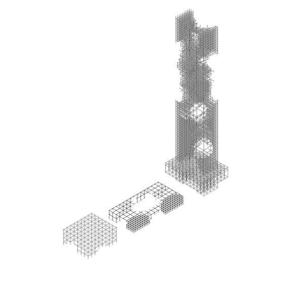
De-constructing the site into Highrise, Plaza & Tram Station.
7 2 3 4 5
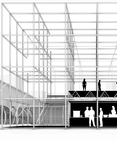
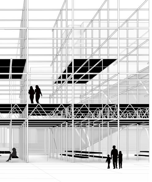
Subtraction of Spaces. Structure, Adaptable Grid. Inhabitation, Containers, Suspended mezzanines, prompt furniture. Order via Circulation Tubes. 1 2 3 4 5
Cold Bridging
Purpose
-Closed loop of Rigid insulation surrounds steel key
-Transfers force through Key Clamp
-Fixes to Steel Brace
-Glazing - Rigid Insulation (perimeter of CHS - ClampContainer)
-Supports Carbon Concrete floor with Steel Clamp (greater surface Area)
x
-Supports corrugated sheet of Container with clamp (greater surface area)
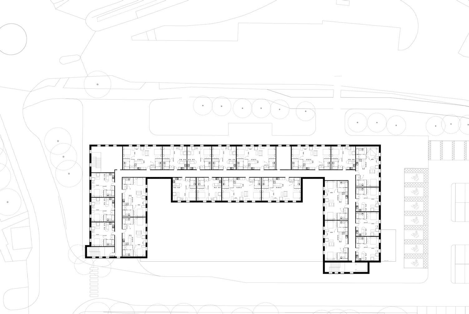
Typical Office Floor Plan: Option 2
10m
Tom Scott Portfolio 8
9 50m South West Section South East Section
Low-income housing Gentrifying City Centre
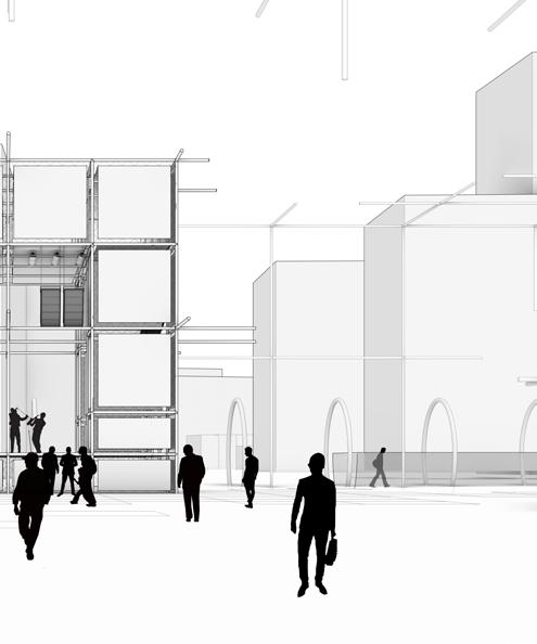
The site sits between 2 defined zones, by bringing in adaptable programmes, the public is open to change the space to their needs. Through decommodification people will have more ownership of their city and district.
The site sits on a Tram network, an opportunity arises for reusing containers from this network for habitual office areas.
Tom Scott Portfolio 10 Tram Station Outdoor seating Stage Stalls Sheltered seating Suspended Lobby Delivery area Tram Line Bicycle/pedestrian path 1 2 3 4 5 6 7 8 9 1000m
Adaptable Programmes 50m
Tram line
Stage
Food Stall
Seating
11
PERSONAL PROJECT
Year: 2024
Type: Communal Project
Research: Natural Swimming pools
Software: Revit, Photoshop
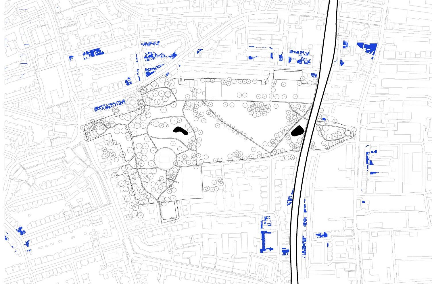
Co-authored by me and my director of my current employment, we are looking to rejuvenate our local area in Hamersmith. Ravenscourt park in Hammersmith sits in a diverse area but is seen to be transformed by gentrification. We propose a 2 stage plan
to rejunvivate its public space and amenities for the community. First, we shall convert the existing pond to a natural swimming pool. Then with the public attention acquired we can move to talks with Network Rail to use their arches for local businesses.
Tom Scott Portfolio 12
1 2
200m
Public Space Lower income households 1 2
Ravenscourt Park Natural Swimming Pond
50m
Converted Natural Swimming
13 Swimming pond Toilets and changing rooms` Baby Changing Disabled Toilets 1 2 3 1 3 2 2
PRACTICE WORK ( HOUSING ) MIXED USE (KEYWORKER HOUSING 1)
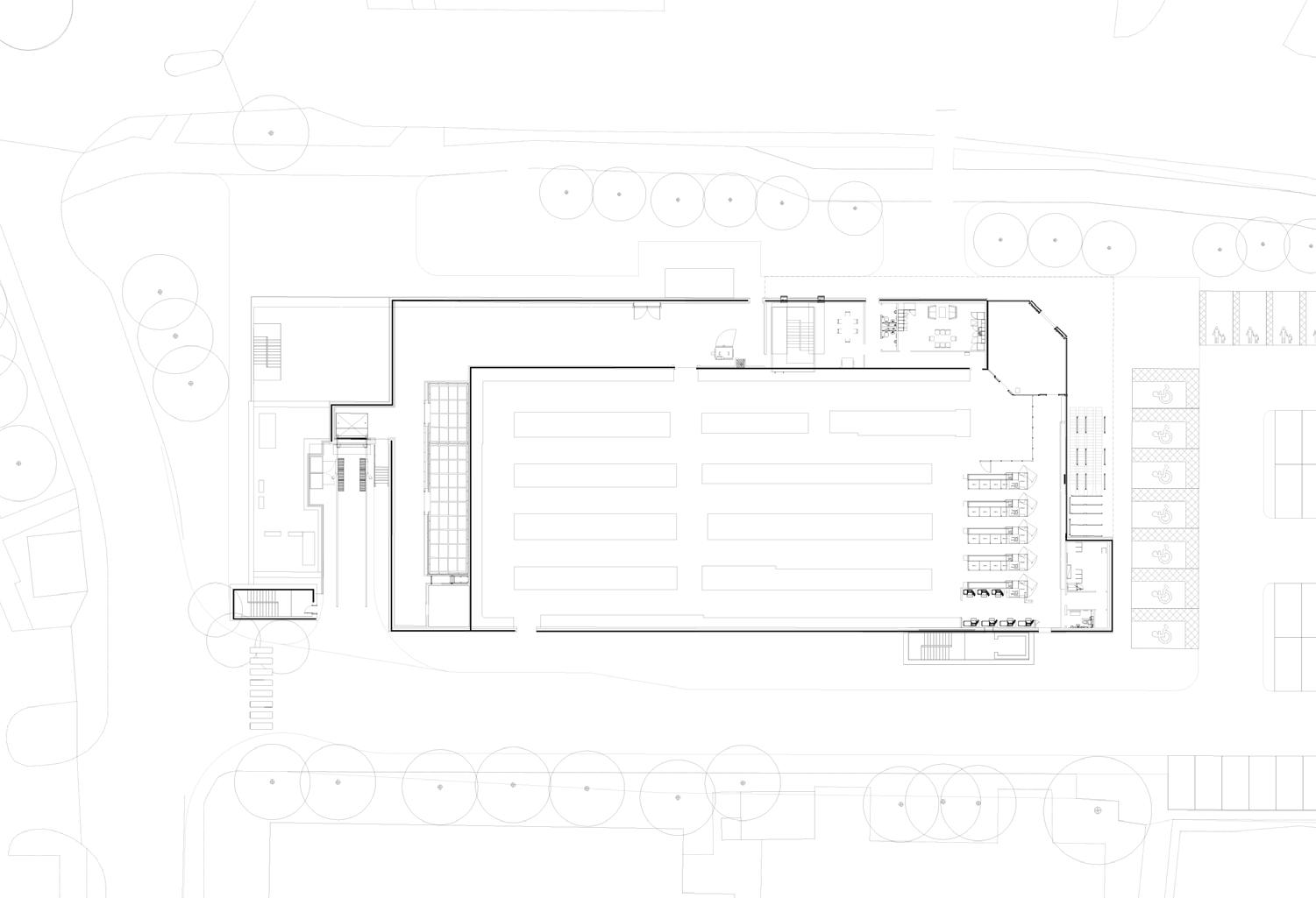
Both projects shown are situated near a transport hub, and are both to be developed on top of an Aldi store. Before understanding massing, site and the human scale, we
worked to see how many units we could fit in. The development was limited due to the restrictions of the Aldi below.
Tom Scott Portfolio 14
1F Limited Site Analysis
GF 10m 100m Train station Private and Public space
MIXED USE (KEYWORKER HOUSING 2)
Year: 2024
Stage: 2-3
Software: Revit, AutoCAD
Involvement: Feasibility Studies
ESS ESS 15 10m 1F
GF Bespoke unit
RESIDENTIAL
Year: 2024
Software: Revit, AutoCAD
Involvement: Site Plans and Illustration
Stage: 3
This residential plot allowed public space between its massing as the plan was not restrictive. However the site is located next to a bus lane which disconnects the site from the community.
SUMMARY OF HOUSING
The mixed housing was located near Transport hubs, but is this just used as home for commuters, and would this further reduce this neighbourhood with little amnesties and industry? The residential housing attempts to fit within the site by providing public space between the massing but the site is disconnected. It seems that my work in providing an extension is the most sustainable achievement, with clients who already like the site and by providing better and new programmes with little demolition.
Tom Scott Portfolio 16 100m
Buslane
Typical Plan
Proposed connections to context
EXTENSION
Year: 2023
Software: AutoCAD
Involvement: Surveyor and Architectural Designer
Stage: 2-4
17
50m
Demolished Reincorporated load bearing walls
Existing GF
New GF
TECHINCAL STUDIES
Year: 2024
Type: Car Park
Software: Revit, AutoCAD
Involvement: Spatial Planning, Modelling, Detailing
Stage: 2-4
This car park was created and drawn according to the system builders construction design. The grid lines are very important and are planned for the system builder with their requirements in mind.
2 Cores are provided on each end so that 40m fire escape distance is provided.
Tom Scott Portfolio 18 G G 15 Panel flush with face of flange Panel flush Cladding panel Cladding panel with end return HEAA200 mitered Cut to web to suit position of column A 1 Panel flush with face of flange Cladding panel Cladding panel with end return HEAA200 mitered A C profile mitered Cassette panel Cassette panel Precast concrete wall Precast concrete wall 3mm steel sheet bent into a C profile 3mm steel sheet bent into a C profile G G 1 15 14 13 12 11 10 9 8 7 6 5 4 3 2 1 G F E D C B A Detail G HEAA200 - Corner Junction at grid intersection M2 1:5 Detail H HEAA200 Column Junction at grid intersection L1 1:5 Detail I C Profile - Corner Junction at SC1 1:5 Key Plan Indication of Detail on L01-03 1:200 H I G 0 20 m Level 00 52248 Level 01 55248 Level 02 58248 Level 03 61248 Level 04 64248 Parapet 66535 A C B Detail section A North Facade and East Facade 1:20 G G 15 15 A 1 1 A G G 1 1 15 14 13 12 11 10 9 8 7 6 5 4 3 2 1 G F E D C I G 0 20 m
Cladding panel with end return HEAA200 mitered Cladding panel Cut to web to suit position of column Panel flush with face of flange Cut to web to suit position of column HEAA200 mitered Cladding panel Panel flush with face of flange Cassette panel 3mm steel sheet bent into a C profile C profile mitered Precast concrete wall Detail I C Profile - Corner Junction at SC1 1:5 Detail H HEAA200 - Column Junction at grid intersection L1 1:5 Detail G HEAA200 - Corner Junction at grid intersection M2 1:5 Detail I C Profile - Corner Junction at SC1 G G 15 Panel flush with face of flange Panel flush Cladding panel Cladding panel with end return HEAA200 mitered Cut to web to suit position of column A 1 Panel flush with face of flange Cladding panel Cladding panel with end return HEAA200 mitered A C profile mitered Cassette panel Cassette panel Precast concrete wall Precast concrete wall 3mm steel sheet bent into a C profile 3mm steel sheet bent into a C profile G G 1 15 14 13 12 11 10 9 8 7 6 5 4 3 2 1 G F E D C B A Detail G HEAA200 - Corner Junction at grid intersection M2 1:5 Detail H HEAA200 Column Junction at grid intersection L1 1:5 Detail I C Profile - Corner Junction at SC1 1:5 Key Plan Indication of Detail on L01-03 1:200 H I G 0 20 m
19 Cladding Panel HEAA180 167 Cladding panel aligned to flange of profile HEAA200 186 Cladding panel Cladding panel Cladding panel aligned to flange of profile Cladding panel aligned to flange of profile Retaining wall 200 Mesh panel Hole for bolt installation tolerance gap 30 18 C A B Detail A HEAA180 to cladding panel detail 1:5 Detail C HEAA200 to cladding panel detail 1:5 Detail E Retaining wall to mesh panel detail (North, East and West Facade) 1:5 Detail section B South Facade 1:20 Detail section C West Facade 1:20 Cladding Panel HEAA180 167 Cladding panel aligned to flange of profile HEAA200 186 Cladding panel Cladding panel Cladding panel aligned to flange of profile Cladding panel aligned to flange of profile Retaining wall 200 Mesh panel Hole for bolt installation tolerance gap 30 NOTES: Drawing issued for specified Do not scale from this drawing purposes. This drawing is Copyright Rev Description P1 Issued for coordination C1 AS BUILT Detail A HEAA180 to cladding panel detail 1:5 Detail C HEAA200 to cladding panel detail 1:5 Detail E Retaining wall to mesh panel detail (North, East and West Facade) 1:5 0 0.2 m 0.5 m Parapet 66535 Level 04 64248 Level 03 61248 Level 02 58248 Level 01 58248 Level 00 58248 Parapet 66535 Level 04 64248 Level 03 61248 Level 02 58248 Level 01 58248 Level 00 58248 Detail Section B Detail Section C Mesh panel aligned to flange of profile Mesh panel 167 HEAA180 Cladding panel Cladding panel aligned to flange of profile Mesh panel aligned to flange of profile Mesh panel 186 HEAA200 Mesh panel Hole for bolt installation Plastic spacer 30 tolerance gap 250 Retaining wall Detail C Retaining wall to mesh panel detail (South Facade) 1:5 Detail B HEAA200 to mesh panel detail 1:5 Detail A HEAA180 to mesh panel detail 1:5