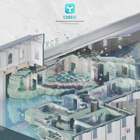
[Research Cluster 5] UCL MArch Architectural Design Portfolio - CUBEIX
CUBEIX
Retrofitting Abandoned Infrastructure for Smart Workspaces
NET ZERO RETROFITTING
WORKFLOW & STAKEHOLDERS
CASE & INSPIRATION
MODULARIZATION ASSEMBLED FURNITURE
PROJECT STATEMENT CIRCULAR WORKFLOW
CASTING & PRINTING
EVOLUTION OF CONNECTION GEOMETRIC DESIGN FURNITURE
MOLD CASTING 3D PRINTING SPEED OPTIMIZATION
USAGE PROCESS DESIGN & PLATFORM
PREVIOUS DIRECTIONS ADDITIONAL MATERIAL
PART A.
RESEARCH
BACKGROUND
NET ZERO AGENDA RETROFITTING WORKFLOW STAKEHOLDERS
NET ZERO AGENDA
The building sector accounts for over 38% of global carbon emissions, with heating and cooling responsible for a major portion of operational energy use. In the UK, over 70% of residential heating demand is linked to outdated infrastructure.
High-energy-consuming areas
While new buildings aim for a U-value of 0.3 W/m²·K, older buildings often exceed 2.0 W/m²·K, leading to significant heat loss and inefficiency. These statistics
underscore the urgent need for egies aligned with the Net Zero agenda, prioritizing scalable, adaptable, and low-carbon retrofit solutions
Barnet Enfield
Pedbridge Barking & Dagenham Havering
Sutton Merton
RETROFITTING CHALLENGES
Window Infrared Image Database
Thermal Performance Study
Retrofitting occupied buildings entails significant challenges, such as high costs, structural limitations, and extended disruption to use.
Early experiments in this project focused on external facade interventions, such as modular insulation panels targeting window areas.
Our thermal imaging study revealed that the most significant heat loss in the building occurred around the windows.
We developed strategies to systematically collect data and establish a database organized according to typical window types in London.
Data Collection Strategy
ABANDONED INFRASTRUCTURE
In metropolitan areas such as London, over 781 public buildings remain derelict, with demolition, clearance, and redevelopment costs averaging over
£480,000 per site. This prompted the project to explore abandoned infrastructures as a more viable testing ground for sustainable retrofitting strategies.
In London , there are 781 Delelict buildings (2022)
High vacancy rate of abandoned building
Sourse:
Utilizing abandoned building provides users with low-rent spaces while addressing the high vacancy rate. On average , it costs
480,000 + to Demolish a small abandoned infrastructure
I’m just starting my business and I’m looking for a venue with low rent and high cost performance to set up my company...
These unused structures simultaneously reflect an underutilized spatial resource and a significant environmental footprint. Repurposing such infrastructures offers an opportunity to address rising land and scarcity, escalating rental prices, and embodied carbon concerns-redefining waste as potential within the urban metabolism.
TRADITIONAL WORKFLOW
The demolition of industrial-scale buildings involves a complex, multi-phase workflow governed by legal,environmental, and technical protocols. Each step——from initial assessments to final site clearance——requires specialized labor, substantial financial input, and strict adherence to regulatory procedures. Particularly, the removal of hazardous materials such as asbestos introduces significant health and logistical constraints. This systemic rigidity and high entry barrier underscore the unsuitability of demolition as a default strategy.
In response, this project explores adaptive reuse as a more viable, sustainable alternative for decommissioned infrastructures, transforming logistical burdens into design opportunities.
STAKEHOLDERS
User Persona
The growing demand for flexible, affordable workspaces among small- medium-sized enterprises highlights a gap in current architectural offerings. These users often face financial instability lacking of
Product Requirements
Their space needs focus on modular, portable, reusable setups with no structural attachments, favoring sustainable, low-maintenance and so on.This condition calls for an adaptable system capable of long-term occupancy certaintyTarget users include startup companies, remote teams, and freelance groups aged 25 to 35. They face budget limits and cannot afford traditional or long-term leases.
25-35 year old Startup Company Remote teams Manager
User Pain Points
Name: Alex Carter
USER
PROFILE
Age: 29
Occupation: Co-Founder Of A Tech Startup (London-Based)
Team Size:
6 People (Remote And Hybrid Work Model)
Budget Limit
Unable to afford traditional renovation or long-term leases
offering essential infrastructure—thermal comfort, water, and electricity—through lightweight, modular, and reconfigurable design strategies.
structural attachment Portable, reusable setup
PROBLEM STATEMENT
By 2050, achieving net-zero carbon emissions requires rethinking not only how buildings are constructed, but how existing spatial resources are reused. Despite growing urban demand for flexible and affordable workspace, a significant portion of the built environment-particularly decommissioned industrial infrastructure——remains underutilized or abandoned.
In cities like London, hundreds of vacant buildings contribute to spatial inefficiency, high land costs, and embodied carbon waste.Conventional demolition of suchstructures is costly,time-consuming, and environmentally damaging due to hazardous material handling and waste generation.
At the same time, many small enterprises lack access toadaptable, low-cost spatial solutions. This gap between resource surplus and user need reveals an urgent opportunity: to retrofit abandoned infrastructure with modular systems that support circular, scalable, and low-carbon reoccupation.
PART B.
PRECEDENTS
CASE
STUDIES & INSPIRATION
MODULARIZATION
ASSEMBLED FURNITURE
BRAIN STORMING
MODULARIZATION 01
Open House/Space10 + Effekt [ Denmark ]
A modular housing system developed by EFFEKT Architects in collaboration with lKEA’s Space10, Open House explores how prefabricated wooden units can be arranged to serve various temporary programs
——co-living, coworking, or even pop-up healthcare. The components are designed for rapid assembly and disassembly, making them adaptable and reusable across multiple contexts.
Sourse: https://space10.com/prjects/urban-village
MODULARIZATION 02
TRIQBRIQ [ Germany ]
TRIQBRIQ is a modular, interlocking building system made from recycled wood waste. Each unit functions as a solid timber brick and can be reused multiple times without loss of structural performance.
The system allows for fast assembly, minimizes construction waste, and enables the full recovery of materials—promoting a closed-loop construction model.
Sourse: https://triqbrig.de/
ASSEMBLED FURNITURE
A research-based brick system combining 3D printing with computational design to optimize thermal performance. The bricks interlock without mortar and feature integrated pockets for vegetation and water
PLUG-IN FURNITURE
Plug-in Furniture System / ICD Stuttgart [ University of Stuttgart ]
Developed at the ICD as part of a research project on spatial adaptability, this furniture system features prefabricated wooden modules that slot into a structural frame without glue or screws. Each unit— flow. Designed for reuse and material circularity, the project aligns with sustainable facade development and ecological urbanism.
ranging from shelves to workstations—is designed for rapid assembly, removal, and reuse. The system emphasizes component reconfigurability and construction efficiency.
Brick By Bit / Victoria Roznowski [ University of Innsbruck ]
OFFICE MODULAR SYSTEM HOME MODULAR SYSTEM
KEIGIO is a modular furniture brand with retro-futuristic industrial designs that adapt to any space. Modular pieces can be customized and tailored to changing needs. The brand emphasizes sustainability
Alfondac is a prototype guest apartment by Catalan architect Aixopluc in a renovated abandoned studio. It features the modular Homeful system, designed for quick assembly and adaptability. The compact design and craftsmanship using traceable materials and eco-friendly processes. KEIGIO offers durable, unique furniture solutions for those who value innovation and expression.
Sourse: https://www.keigio.com/catalog2024english
integrates storage, sleeping, and enclosures, maximizing open space while emphasizing sustainability with eco-friendly materials and efficient construction.
The initial phase of design focused on developing facade-based interventions——particularly thermal modules for window retrofitting. Through a series of iterative tests, limitations related to installation complexity structural dependency, and thermal inefficiency were gradually revealed.
This page documents the conceptual transition from these early trials toward a more holistic system: A fully modular,reconfigurable spatial framework designed to operate independently of the building envelope.
The central sketch marks a critical pivot in the design process, initiating the development of Cubeix as a systemic spatial retrofit strategy rather than a facade enhancement solution.
PART C.
DESIGN
STATEMENT
PROJECT STATEMENT
CIRCULAR WORKFLOWS
CUBEIX: PROJECT OVERVIEW
Cubeix proposes a spatial retrofit system for vacant and underutilized infrastructures, aiming to transform them into affordable, low-carbon smart workspaces. The project addresses two urgent challenges: the inefficiency of conventional demolition and the shortage of adaptable work environments for small urban enterprises.
Instead of altering the existing structural envelope, Cubeix introduces modular interior components that function independently from the host building. Each unit integrates thermal insulation, water and electrical access, and workspace functions, assembled through a dry, reconfigurable construction method.
Designed with circularity in both material and operation, the system’s components are reusable, repairable, and digitally adaptable to user needs and environmental inputs. Through this approach, Cubeix redefines abandoned buildings as latent spatial assets, contributing to a net-zero urban future.
CUBEIX: PROCESS DESIGN
The system is designed with full circularity in both material and operational terms: components are reusable, repairable, and digitally configurable to respond to user needs and environmental inputs.
Supported by infrastructure data analysis—including sunlight, noise, and insulation performance—the design process also integrates user requirements such as functions, number of employees, and spatial
preferences. These inputs generate optimized space layouts, which are then realized through modular assembly methods. The resulting units are fully customizable, removable, and adaptable,
transforming abandoned buildings from liabilities into latent spatial assets for a net-zero urban future.
CUBEIX WORKFLOW
The following outlines Cubeix’s workflow for creating adaptable, data-driven spatial layouts:
1.Cubeix combines user needs with real-time environmental data to create optimized layouts.
2.Users provide basic info and choose a site; environmental factors like daylight, airflow, noise, and views are gathered and analyzed.
3.A backend engine adjusts priorities and modular options to produce a customizable, low-impact plan tailored to the site and users’ needs.
PART d.
BACK END COMPUTATION
ANALYSIS FRAMEWORK
DEVELOPMENT PROCESS
BACKEND OPTIMIZATION
SPATIAL GENERATION
ANALYSIS FRAMEWORK
The goal of the backend is to convert data into actual output. After the user selects the appropriate factory, physical environment data is first collected from the factory, and then the distribution of environmental data is determined through software simulation.Next, five types of environmental data are integrated to determine a reasonable spatial layout plan.
After that, a genetic algorithm is used to derive the optimal furniture layout plan. The plan is then updated in real time based on user feedback. Additionally, other environmental factors (such as visibility, direct sunlight, and exterior wall insulation) must be considered for their impact on building facade renovations.
Grasshopper
Eddy3D
OVERVIEW + PROCESS
First, the customer selects a factory to determine its geographical location, and then obtains the factory’s
model data based on the scanned information. In the next stage, the factory information is matched to the
physical environment database and then the physical environment is analysed by a computer.
Finally, the floor plan is integrated to generate basic floor plan distribution information.
Generating Outcomes
ENVIRONMENTAL INFORMATION INPUT
Environmental information is an objective condition of a building. We analyse five modes—DAYLIGHT, AIRFLOW, NOISE, CONNECTIVITY, and VIEW POTENTIAL
Mindmap: From Environment to User-Centered Design
Based on the physical environment of the building in order to produce designs based on the actual needs of users in the next step. It can also be used for machine learning to support data in the subsequent user feedback stage.
DAYLIGHT ANALYSIS NOISE
Daylight analysis evaluates indoor lighting distribution by simulating the path of natural light as it travels through a building. Based on building geometry, sun position, and material reflectance characteristics,the system tracks the irradiation and reflection pro
cesses of light after it enters a space, recording the distribution of illuminance at various locations. The results are used to determine the uniformity of lighting in a space and to guide window placement, shading, and lighting design.
Noise analysis simulates the propagation path of sound sources in space to assess the distribution of noise indoors. The system calculates the attenuation and diffusion of sound based on the location of the sound source, spatial geometry, and reflective
surface materials, and records the noise intensity at each point. The results are used to identify areas of concentrated noise and guide the design of acoustic partitions, sound-absorbing materials, and functional zoning.
VIEW POTENTIAL CONNECTIVITY
View Potential Analysis assesses the number of visible external openings and the degree of visibility at each location by simulating the range of sightlines projected outward from points within the interior. The system considers the location of windows and obstructing elements in the building to calculate the width of the visible range at each point. The results are used to identify areas with good and restricted visibility within the space, assisting in spatial layout, functional division, and optimisation of user comfort.
Connectivity analysis assesses overall accessibility by calculating the distance and path complexity between points in a space. The system generates connected paths from each point based on spatial geometry and obstacle distribution, and uses this to
determine relative centrality and ease of access. The results are used to identify transportation hubs and marginal dead zones, assisting in path optimisation and spatial layout adjustments.
AIR FLOW DATA REDUCTION
Air Flow Analysis evaluates natural ventilation effectiveness by simulating airflow paths and velocity distributions within a space. The system calculates airflow stagnation and movement in different areas based on window positions, wind direction, and spatial geometry, identifying ventilation dead zones and high-velocity channels to optimise window opening strategies and indoor thermal comfort design.
The final stage translates environmental simulations into weighted programmatic layouts. Each spatial type— office, meeting, lounge, storage, or exhibition—is assigned priorities based on day light, airflow, noise, connectivity, and view potential. This weighted system allows environmental performance to directly inform spatial distribution, ensuring that functions align with optimal conditions.
DAYLIGHT ANALYSIS
Natural lighting is a key parameter in determining workspace quality, user comfort, and passive heating potential. The analysis identifies areas with the strongest direct sunlight by simulating conditions throughout the day. Zones with insufficient daylight are excluded from module placement, while well-lit areas are optimised for active use and potential energy savings.
NOISE ANALYSIS
Noise mapping is conducted at different times of the day to capture fluctuations in sound levels from nearby industrial and traffic sources. High-noise zones are avoided when placing work-intensive modules, while quieter areas are designated for focused or collaborative activities. This filtering fosters an acoustically comfortable environment and supports a functionally diverse layout configuration.
Figure 01-08
Noise distribution across the factory interior (5 AM–12 AM).
Sound mapping reveals active and quiet zones, guiding spatial allocation
VIEW POTENTIAL ANALYSIS
Visibility into the interior from external public areas is assessed to distinguish between high-privacy and high-exposure zones. Modules for confidential or individual use are placed in low-visibility areas, while highly visible zones are designated for communal or public-facing functions. This arrangement ensures a balanced integration of openness and privacy within the modular system.
· Visibility analysis of the factory interior (5 AM–12 AM).
· Guiding the spatial balance between privacy and exposure in modular design.
High visibility
Suitable for Privacy Suitable for Public
Low visibility
Moderate visibility
Figure 01-08
AIRFLOW ANALYSIS
Airflow simulation is performed at multiple vertical sections to accurately identify passive ventilation opportunities. Areas with insufficient air circulation are deprioritized or supplemented with mechanical systems, while well-ventilated zones naturally support airflow and reduced energy use. This ventilation analysis directly informs both module arrangement and opening orientations.
>0.5m/s
0.4-0.5m/s
0.2-0.3m/s
0-0.1m/s
Figure 01-05
· Figures 01–05. Airflow simulation across vertical sections (Ground to +4 m).
· Informing module placement and opening orientation through passive ventilation mapping.
Using this data, program can derive a relatively reasonable spatial layout.
WEIGHTED LAYOUT GENERATION
The final spatial layout is generated through a weighted evaluation of five key environmentalparameters:daylight,noise, airflow, view, and connectivity. Each parameter is assigned a weight based on user preferences and programmatic priorities.
These weights influence the desirability of each spatial cell, which is visualized as a color-codedheatmap. The system then organizes modules accordingly, prioritizing comfort, functionality, andenvironmental response.
This method ensures that the final plan adapts not only to site conditions but also to user needs and usage scenarios.
AUTOMATED INDOOR ANALYSIS
To ensure optimal performance and spatial comfort, the CUBEIX system incorporates multiplelayers of indoor environmental analysis. Each site is evaluated based on five key parameters:Daylight, Noise, Airflow, Connectivity, and View potential.These factors are extracted through parametric simulations and spatial sampling, and serve ascritical inputs for module placement and density strategies.
The results guide the system’s response to site-specific conditions, ensuring functional, user-sensitive layouts.
Open field, no route
The route was extended, thus forming functional areas divided according to demand.
The two doors are connected to form the core route
LEVEL TRANSFER
Multi-level comprehensive floor plan generation. First, multiple factory information is stored in the database and called up according to user requirements. After selecting a factory, Grasshopper analyses its physical environment information. By adjust
ing parameters, the system produces diverse floor plan combinations. These outcomes reveal how varying inputs create distinct spatial organizations, forming a flexible toolkit for adaptive reuse and modular transformation.
Different parameters generate different spatial combinations
LAYOUT POINT SELECTION
To obtain the optimal floor plan layout, we used a genetic algorithm to calculate the comprehensive values of five attributes: Daylight, Noise, Airflow, Connectivity, and View potential. We then scored the results to obtain a suitable layout position.
GENERATION PROCESS
Connectivity analysis assesses overall accessibility by calculating the distance and path complexity between points in a space. The system generates connected paths from each point based on spatial geometry and obstacle distribution, and uses this to determine relative centrality and ease of access. The results are used to identify transportation hubs and marginal dead zones
2D TO 3D GENERATION
The analysis process translates two-dimensional environmental data into a three-dimensional evaluation framework. By slicing the building at 500 mm height intervals, each layer undergoes simulation
Conducting sliced
Slice the building at 500 mm height intervals and run an environmental analysis of daylight, noise, view potential, and connectivity. The stacked results form acomprehensive spatial profile, revealing how environmental performance changes vertically across the structure.
PART E.
PHYSICAL PRODUCT EVOLUTION
EVOLUTION OF CONNECTION
GEOMETRIC DESIGN
FURNITURE
DESIGN EXPLORATION
The initial stage of this project focused on the design of building façades, exploring how to achieve a balance among three key functions: Thermal insulation, daylighting, and privacy. As the “skin” of a building, the façade plays a critical role in determining the comfort level and energy performance of the indoor environment.
(Detailed façade design schemes will be presented in the appendix.)
However, as the exploration progressed, we found that the façade design offered limited room for innovation and practicality. Its flexibility for design adjustments was low, making it difficult to meet diverse user needs, and the complexity of technical implementation gradually became a bottleneck for project advancement.
Based on these insights, the project team decided to shift its focus towards the design and development of interior spaces, aiming to create office environments that can be flexibly customized according to user needs.
At this stage, the design concept was centered on “modularity,” with primary design elements consisting of combinable units resembling Lego-like cubes. This early design feature inspired the project’s name — cubeix.
EXPLORATION AND INNOVATION OF MODELS
This study explores ten modular designs, aiming to investigate the differences and potential of modules in terms of functionality, aesthetics, and adaptability through various geometric logics and connection methods. Each design starts with a single unit, which is then stacked, joined, or deformed to generate new modular forms. Diverse assembly strategies are introduced, such as regular stacking, networked connections, magnetic joints, and rotational folding.
method
Connection
DESIGN EXPLORATION 1
The design starts with the same basic unit and forms unique modules through two different combinations.
Model 1 is formed by regular stacking, while Model 2 develops into a more permeable, intertwined module.
DESIGN EXPLORATION 2
This module is still assembled through stacking, but its form is more distinctive and aesthetically refined. In aggregation, it creates an open, network-like structure with strong potential for expansion and diversity, though challenges remain in assembly and stability.
DESIGN EXPLORATION 3
This module is mainly composed of stacked rules, which are stable but slightly cumbersome. Its round hole structure not only enhances load-bearing capacity and stability but also makes it possible to embed functional modules. However, it lacks openness and aesthetics, and is more functional and practical.
DESIGN EXPLORATION 4
This module features a grid framework and holes, which, when assembled, form a grid structure that is highly stable and efficient. It can also be embedded with functional units to meet specific needs, but its form is relatively simple and its aesthetic appeal is limited.
DESIGN EXPLORATION 5
This module features organic curved surfaces, with a flowing shape and striking aesthetic appeal. When assembled, it can form a complex surface, showcasing diversity. However, it is difficult to manufacture and assemble, and its efficiency and functionality are relatively lacking.
DESIGN EXPLORATION 6
This module features a frame structure with internal channels for easy vertical expansion. It is highly stable, has a clear assembly method, and is suitable for forming a regularized system. However, its appearance is somewhat engineering-oriented, with limited aesthetic appeal and variability.
DESIGN EXPLORATION 7
This module primarily uses rotary connections, with a circular hole structure that enhances load-bearing capacity and allows for the embedding of functional units. Its connection method is ingenious, its form is aesthetically pleasing, but it is relatively expensive and has limited openness.
DESIGN EXPLORATION 8
Magnetic connection makes it convenient. Each unit is assembled from smaller sub-modules, reducing overall manufacturing costs. Its frame
structure provides stability and clear assembly logic, suitable for forming a regularized system. However, its aesthetics and variability are limited.
DESIGN EXPLORATION 9
This module breaks down the unit into sections and processes them in a folded manner, with each module forming an overall three-dimensional structure.
It has a neat and aesthetic appearance, but the processing and manufacturing costs are high, and its openness is limited.
DESIGN EXPLORATION 10
This module adopts a lightweight plate structure and can be quickly assembled using magnetic connectors. Not only does it adapt to more functional requirements, it also has a high aesthetic appeal. It is lightweight, flexible, and stable, it is suitable for standardized systems.
DESIGN OVERVIEW
This design explores modular design through nine variants and six connection methods. Evolving from a basic stacking structure to an interlocking systemthese modules demonstrate diverse performance in terms of adaptability, aesthetics, cost-effectiveness, efficiency, structure, and assembly, laying the foundation for future building facade and space design.
SUMMARY OF MODELS
The design study consolidated nine modular variants and six connection methods, ranging from stacking and plugging to rotational and magnetic systems. Each prototype was evaluated in terms of adaptability, efficiency, cost-effectiveness, structure, and assembly performance.
Some modules emphasize stability and load-bearing capacity, while others focus on flexibility and rapid assembly. Together, these outcomes establish a systematic framework for Cubeix, providing scalable, reconfigurable solutions that integrate functionality with spatial adaptability.
CUBEIX SYSTEM
Cubeix is a modular system developed to address the need for flexible, lightweight, and customizable interior interventions.
Each component variation explores a different logic of assembly, from structural reinforcement to spatial adaptation, creating a toolkit of parts that can be reconfigured according to context.
COMPONENT 01 BASIC FRAME MODULE
The base frame module functions as the structural core of the Cubeix system. Designed as a 30×30×30 cm unit, it provides the essential framework to which all other modules can be attached. Its grid-like geometry allows for stable aggregation and ensures compatibility across different product types. Serving as both connector and support, the base frame is the foundation for adaptable assemblies, enabling Cubeix to operate seamlessly across scales from furniture to interior partitions.
INSTALLATION METHOD
COMPONENT 02 WALL MODULE
The wall panel module attaches directly to the base frame using magnetic joints, forming lightweight yet stable enclosures. Each panel can be easily mounted or removed, allowing walls to be rearranged without permanent intervention. This flexibility makes spatial
INSTALLATION METHOD
layouts highly reconfigurable, while the magnetbased connection system ensures precision and repeatability. The wall panel provides a fundamental layer for defining interior boundaries within the Cubeix system.
COMPONENT 03 CEILING LIGHT MODULE
The ceiling lighting module clips onto the base frame, transforming structural grids into luminous planes. Integrated fixtures provide consistent illumination while maintaining the modular character of the system. Its detachable nature allows lighting to be
INSTALLATION METHOD
reconfigured as spatial needs change, minimizing reliance on fixed infrastructure. By embedding lighting within the Cubeix framework, the module demonstrates how technical functions can merge seamlessly with structural units.
COMPONENT 04 SHELF MODULE
Inspired by pegboard systems, the shelving module integrates storage within the Cubeix framework. The base unit incorporates perforations that allow smaller boxes, trays, and shelves to be slotted and locked into place. This logic of interchangeable
INSTALLATION METHOD
accessories creates a customizable toolkit for organizing space, from domestic interiors to work environments. By embedding storage directly into the modular grid, the shelving module expands the functional adaptability of Cubeix components.
COMPONENT 05 SERVICE MODULE
The service module attaches securely to the base frame, serving as a channel for utilities such as water, electricity, and gas. Positioned primarily in ceiling configurations, it provides an organized framework for infrastructure distribution. By embedding technical
INSTALLATION METHOD
systems within modular units, the service module reduces complexity in retrofit applications, while maintaining flexibility for future adaptation. This integration highlights the capacity of Cubeix to merge structural, spatial, and infrastructural functions.
COMPONENT 06 WINDOW MODULE
The window module introduces transparency and ventilation within the Cubeix system. Constructed from a secondary frame that connects seamlessly to the base unit, it allows for glazing or operable openings to be incorporated into modular assemblies.
INSTALLATION METHOD
The design balances enclosure and openness, enabling partitions to admit light and air while maintaining structural compatibility. As an adaptable boundary element, the window module enhances environmental quality and spatial experience.
COMPONENT COMPOSITION
Beyond single units, Cubeix demonstrates its versatility through aggregated assemblies such as tables, chairs, planters... By combining base frames with specialized modules, everyday furniture and spatial configurationsemerge from the same toolkit.
INSTALLATION METHOD
These compositions illustrate the scalability of Cubeix—from functional objects to architectural systems—highlighting its potential to support diverse interior programs through recombination and customization.
PART F.
MANUFACTURE
CASTING & PRINTING
MANUFACTURING EVOLUTION
MOLD CASTING
3D PRINTING
SPEED OPTIMIZATION
EVOLUTION OF FABRICATION
The project explores fabrication through three stages: from 3D-printed molds combined with experimental materials, to fully 3D-printed structures, and finally to optimized printing processes. The design objectives are efficiency, affordability, customization, and lightness. To address these aims, multiple production approaches were tested, balancing speed, precision, and cost, leading toward a refined and scalable fabri
cation system.
1. CASTING MOLDS WITH EXPERIMENTAL MATERIALS
The first method introduced 3D-printed molds filled with unconventional materials such as mycelium and expandable polystyrene. This process simplified prototyping by enabling simultaneous casting through reusable molds. The approach highlighted potential for batch production while also opening exploration into biodegradable and lightweight alternatives, situating material research as a critical component of modular fabrication strategies.
Casting mold 1
Casting mold 2
1. CASTING PROTOTYPE CASTING TESTS
Prototype casting tests were conducted using 3D-printed molds to evaluate material behavior and accuracy during fabrication. The process demonstrated how experimental materials interact with the mold geometry, producing components with
Use a 3D printer to fabricate the mold body
varying levels of precision and surface finish. These tests highlighted both the opportunities for simplified batch production and the limitations in achieving the high tolerances required for modular assembly.
Fill the interior with raw materials and process it through the designated technique
1. CASTING MYCELIUM
As part of the project’s circular design agenda, mycelium-based biocomposites were evaluated as a potential casting material. Mycelium offers biodegradability, low embodied carbon, and thermal insulation.
However, experiments revealed key limitations: growth failures from environmental instability, long cultivation periods, and high costs. While bio-based materials remain promising, the current prototype phase prioritizes more controllable, scalable alternatives like low-carbon concrete or recycled aggregates. Material selection continues to balance sustainability, performance, and feasibility.
Polystyrene can expand up to ten times its original volume by releasing pentane gas trapped inside the beads when steamed above 80°C. In manufacturing, the beads first undergo pre-expansion to about half their final volume, then are heat-fused in a mold to reach their full size.
As part of the project’s circular design agenda, mycelium-based biocomposites were evaluated as a potential casting material. Mycelium offers biodegradability and low embodied carbon.
However, experiments revealed key limitations: growth failures from environmental instability, long cultivation periods, and high costs. While bio-based materials remain promising, the current prototype phase prioritizes more controllable, scalable alternatives like low-carbon concrete or recycled aggregates. Material selection continues to balance sustainability, performance, and feasibility.
uEPS Expansion Process
Steam heating experiment
Heating mold design
Dual-layer internal circulation heating
uEPS gradually expands under heat, with particle size increasing from 2 to 30 minutes, producing a lightweight and porous texture suitable for rapid prototyping. Across a heating cycle of 2 to 30 minutes, the beads progressively increase in volume while reducing density, creating a lightweight structure with improved thermal and acoustic properties.
Prototype testing
conception
Expandable polystyrene
The thermodynamic analysis dia gram is obtained.
1. CASTING CHALLENGES OF METHOD
Mold casting revealed significant constraints. Components often lacked smoothness, production cycles were lengthy, and overall precision was insufficient for modular assembly requirements. While the method showcased opportunities for sustainable ex-
perimentation and parallel mass production, its limitations in accuracy and efficiency rendered it unsuitable for immediate application, positioning it instead as a speculative alternative.
2. 3D-PRINTING HIGH-PRECISION PROTOTYPE
A second approach focused on fully 3D-printed components. Experiments with different nozzles achieved significantly higher precision, demonstrating improvements over mold-based casting. However, this method also introduced challenges, such as extend-
ed printing times, material waste from support structures, and post-processing demands. The central task became balancing the high accuracy of the method with the efficiency required for modular scalability.
3D Printing Nozzle Experimentation
2. 3D-PRINTING OPTIMIZING THE MODEL
The fabrication process advanced through redesigning component geometry to reduce both material consumption and printing time. Optimization produced lighter units while retaining structural integrity, accelerating production cycles
Reduce print support
and facilitating assembly. These refinements aligned with the overarching goals of efficiency and adaptability, demonstrating the potential for highly responsive digital-to-physical workflows in modular construction.
Rebar orientation is determined by the angle of the previously printed layer, ensuring structural efficiency while minimizing material use.
2. 3D-PRINTING OPTIMIZING THE REBAR
Structural optimization extended into reinforcement logic inspired by rebar. Through design modifications, printing time and material usage were minimized while maintaining strength and stability. This investigation illustrated how performance and efficiency can be balanced, reinforcing the broader aim of creating modular components that are lightweight, precise, and suitable for scalable architectural applications.
rebar experiment
Lightest
COMPARATIVE CONCLUSION
The comparison between methods indicated that fully 3D-printed fabrication offered superior precision and adaptability, making it the more practical solution for modular applications. Mold-based casting remains avaluable area of material exploration, particularly for sustainability-driven research, but its limitations restricted implementation. Ultimately, Method 2 was selected as the primary fabrication pathway for further development.
PART G.
UI & UX
USER SIDE
USAGE PROCESS
DESIGN & PLATFORM
SIMULATED SCENE
STEP BY STEP
USERFLOW
Through User Interface (Ul) and User ExperienceUX) design, we created two logical processesrepresented in flowcharts, depicting frontend useractions and backend system responses.
STEP BY STEP
This flowchart represents the backend processesexecuted in response to user actions, includingdata processing,system responses, and backendpperations that support the user journey
USER FLOW
This flowchart outlines the steps users take wheninteracting with the application on the frontend.ncluding decisions, actions, and interaction paths.
These two flowcharts work together to ensureseamless integration between the frontend userexperience and the backend system functionalityaligning user needs with system capabilities.
UI UX DESIGN
Cubeix delivers an all-in-one application tailored tosimplify and execute the creation of spatial layouts. By integrating cutting-edge mobile devicetechnologies, the platform ensures smoothfunctionality and adaptability.
With its intuitive user experience and easy-to-navigate interface, Cubeix streamlines the entireprocess,empowering users to efficiently design andoptimize spatial layouts with confidence.
We developed a platform to gather user requirements, wherewe collect key information during user registration, such asGPS data, to better understand their location and preferences
USER INPUT LOCATION
SELECT SIZE PAGE
Users select the number of people they need to accommodate based on their own requirements, which will determine the size and functionality of the venue.
SELECT THE REQUIRED NUMBER OF PEOPLE TO DETERMINE THE AREA
CUBEIX
FUNCTION SELECTION PAGE
Users select the functions initially set for the space. Different spaces offer different room types to choose from, and then provide some recommended options.
USERS SELECT THE REQUIRED FUNCTIONS
User needs influence the selection of spatial functions.
Manufacture
SITE PICKER PAGE
Users can search for favoured areas on the map interface anddirectly compare factory locations and rental costs. In addition,they can filter the search results based on preferences such asfactory size, rental costs or nearby amenities.
Users can select different factories to obtain different information, which facilitates further selection.
FACTORY SELECTION PAGE
Users can obtain detailed information about a factory by clicking on it on the map. After comparing the factories, they can select the one they want to use, and the back end will call up the information about that factory for the next step.
SIMULATION PAGE
After the user selects the target factory, the system calls up the physical environment data of that factory for analysis and performs a preliminary simulation of the floor plan for the customer’s reference.
THE SYSTEM COMPREHENSIVELY PROCESSES USER INPUT.
STYLE SELECTION PAGE
On this page, the system will recommend space styles to users. Of course, users can also choose their preferred style options, and the system will generate a space layout based on these selections.
SYSTEM GENERATED PAGE
After the user has made all their selections, the system enters the calculation phase, where it processes the inputted area size, type, style, etc., and generates a preliminary spatial layout plan.
SPACE GENERATION PAGE
On the space generation page, the system arranges the space and wall layout based on the number of rooms required by the user, and automatically calculates the optimal path to organise the passageways.
The back-end calculates and generates walls while simulating paths and enclosing spaces.
AUTOMATICALLY EVALUATE THE SPATIAL SCORE
SPACE ADJUSTMENT PAGE
On the space adjustment page, users can modify the number of room types required after the system generates recommendations, and draw and modify floor plans as desired. USER ADJUSTS NUMBER OF ROOMS
INTERIOR LAYOUT PAGE
On the indoor layout page, you can view the floor plan after the system has automatically arranged the interior, and you can also adjust the layout by conversing with AI.
Ventilation Test Ensure
Daylighting Test
Window Layout
FURNITURE ADJUSTMENT PAGE
On the furniture adjustment page, users can customise details such as the colour and quantity of furniture. They can also adjust the number of functional rooms.
FURNITURE REARRANGEMENT
PRODUCT SELECTION PAGE
After users complete the floor plan layout and furniture selection, all items are added to the shopping cart for screening and final purchase.
FURNITURE REARRANGEMENT
CASE 01: PUBLIC OFFICEOFFICE
The system is designed with full circularity in both material and operational terms: components are reusable, repairable, and digitally configurable to respond to user needs and environmental inputs.
Furniture components
Supported by infrastructure data analysis—including sunlight, noise, and insulation performance—the design process also integrates user requirements such as functions, number of employees, and spatial
CASE 02: LAB
CASE 03: MEETING ROOM
CASE 04: READING ROOM
CASE 05: REST SPACE
PART h.
APPENDIX
COMPUTATIONAL METHOD
PREVIOUS DIRECTIONS
ADDITIONAL MATERIAL
ARCHITECTURAL SPACE SEGMENTATLON
Use Grasshopper to remodel the building, breaking it down into multiple components such as walls, windows, and floors, to facilitate subsequent analysis.
Architectural space segmentatlon
DAYLIGHT ANALYSIS
Sunlight analysis was simulated using honeybee to determine the optimal lighting areas for the building for zoning purposes.
Spatial Analysis In Architecture - Daylight
NOISE ANALYSIS
Noise analysis utilises simulations of sound source
Spatial Analysis In Architecture - Noise
VIEW POTENTIAL ANALYSIS
Spatial Analysis In Architecture - View Potential
CONNECTIVITY ANALYSIS
Connectivity analysis calculates the path from a point
Spatial Analysis In Architecture - Connectivity
AIRFLOW ANALYSIS
Airflow analysis uses London climate data to calcu-
Spatial Analysis In Architecture - Airflow
FURNITURE LAYOUT
Finally, the physical environment is reanalysed, and a genetic algorithm is used to automatically determine the optimal layout of the furniture.
Furniture Layout
AUTOMATED OUTDOOR ANALYSIS
In addition to interior data, the Cubeix system incorporates site-specific outdoor analysis to understand environmental exposure and visual permeability. Direct sunlight penetration is simulated
to identify optimal zones for passive lighting,thermal gain, or shading. Simultaneously, outward-to-inward visibility is analyzed to determine which areas of the interior are exposed to public or street-facing views.
These insights inform the positioning, orientation, and enclosure level of modular units, ensuring that layout decisions respond not only to interior function but also to external spatlal dynamics.
THERMAL ANALYSIS
Thermal imaging is used to evaluate the distribution of heat loss across the existing building envelope.
The analysis reveals crilical inefficiencies around windows, door frames, and facade junctions, where heat dissipation is most significant.
These findings inform the themal performance requirements of the Cubeix system. Modules are placed to avoid high-loss zones or enhance insulation
where necessary, ensuring energy efficiency and thermal comfort within the retrofitted space.
THERMAL GRID TRANSLATION
A thermal map of the existing building envelope is analyzed to identify heat loss patterns. Using color channels (RGB - XYZ - ClE coordinates), a
computational workflow translates visual temperature gradients into a density-responsive grid system.
Areas with high thermal leakage—typically highlighted in red—are assigned a denser module configuration to improve insulation and reduce energy loss. Conversely, cooler areas require fewer components, optimizing material efficiency. This grid functions as a data-driven framework for modular placement and performance control.
WINDOW STRATEGY EVOLUTION
The design initially explored a system of window-mounted modules that attached externally to existing openings. However, issues of structural instability, complex installation logistics, and high fabrication costs rendered this strategy unfeasible.
The approach was then redefined: instead of attaching to existing windows, the windows themselves would be removed and replaced with Cubeix components that act as both structural and
spatial anchors. These modules not only substitute the functional role of windows but also serve as entry points from which the new interior system “grows” into the building.
This shift simplifies construction, enhances modular integration, and repositions the window from a passive boundary to an active threshold of transformation.
FUNCTIONAL MODULE
The window module comprises multiple subcomponents of varying sizes, designed to reduce glare from direct sunlight while permitting controlled natural illumination into the interior.
Before installing
After installing
Window Module
GEOMETRIC TYPOLOGY DEVELOPMENT
The spatial system is composed of modular units whose geometry defines the assembly logic, spatial rhythm, and environmental performance.
The final design, selected through comparative evaluation, harmonizes manufacturability with formal expression, delivering both functional efficiency and a unified visual language.
A series of geometric iterations were developed and tested, ranging from rectilinear to cellular and faceted configurations. Each typology was evaluated against criteria including material efficiency, structural stability, inter-module connectivity, and spatial adaptability.
CONNECTION LOGIC AND SYSTEM FLEXIBILITY
The Cubeix system employs a dry-assembly method that enables rapid, reversible construction. Each unit incorporates an interlocking mechanism, with one side slightly protruding and the other recessed. When inserted and rotated 90°, the modules lock together without the need for tools or adhesives.
This mechanical joint enables components to be connected, repositioned, or detached. As a result, the system is modular and reconfigurable, capable of adapting to diverse spatial conditions and user requirements. Modules can be reused across sites or reassigned when the user or program changes.
FUNCTIONAL MODULE
PIPE
FURNITURE SYSTEM VISUALIZATION
Use any combination of the madules
SCALE MODEL PROTOTYPING
To evaluate the structural stability and interlocking performance of the modular design, scaled physical models were 3D printed and assembled.
These prototypes facilitated the assessment of component geometry, rotational locking behavior, and stacking tolerance. Various angles and load conditions were physically simulated to examine overall module stability.
The testing process validated the feasibility of the proposed connection system and informed subtle refinements in module form, dimensions, and joinery details prior to full-scale fabrication.
CUBEIX
Retrofitting Abandoned Infrastructure for Smart Workspaces