
7 minute read
Potentiometer 1k

2) Components Details The given below is the detailed information of the components used in this project. a) Arduino UNO Rev3: The Arduino Uno is a microcontroller board that uses the ATmega328P microprocessor (datasheet). It contains 14 digital input/output pins, 6 analogue inputs, a 16 MHz ceramic resonator (CSTCE16M0V53-R0), a USB connection, a power connector, an ICSP header, and a reset button. It comes with everything you'll need to get started with the microcontroller; simply plug it into a computer with a USB connection or power it with an AC-to-DC converter or battery. You may experiment with your Uno without fear of making a mistake; in the worst-case situation, you can replace the chip for a few dollars and start over..
Figure 2: Arduino UNO Rev3
Advertisement
b) Ultrasonic Sensor: An ultrasonic sensor is an electronic device that emits ultrasonic sound waves and converts the reflected sound into an electrical signal to determine the distance between a target object and the sensor. Ultrasonic waves travel at a quicker rate than audible sound, which humans can hear. Ultrasonic sensors, as their name suggests, use ultrasonic waves to determine distance. The sensor head sends out an ultrasonic wave, which is reflected back to the sensor head. By monitoring the duration between emission and reception, ultrasonic sensors can determine the distance to the target.
Figure 3: Ultrasonic Sensor
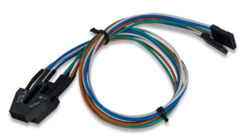
c) IR Sensor: The term "infrared" refers to a beam of infrared light which is used to detect the presence of an object. It works in the same way as ultrasonic sensors, but instead of using sound waves, it sends out infrared signals. Infrared proximity sensors have an IR LED that emits light and a light detector that detects reflected light. It has a signal processing circuit integrated in that determines an optical spot on the PSD. The IR LED emitter produces infrared light. When a beam of light strikes an object, it is reflected at an angle. The light detector will receive the reflected light. The position/distance of the reflected object is determined by the sensor in the light detector.
Figure 4: IR Sensor

d) LCD Display: A liquid-crystal display (LCD) is a flat panel display, electronic visual display (EVD), or video display that uses the light modulating characteristics of liquid crystals. Light isn't emitted by liquid crystals in any way. This arrangement uses a 2-line, 16-character LCD display. It uses a 4-bit interface. The characters showing the process occurring are sent to the screen to display.
Figure 5: 16x2 LCD Display
e) DC Gear Motor: A gear motor combines a motor and a gearbox into one unit. When a gear head is added to a motor, the speed is reduced but the torque output is increased. In terms of gear motors, the most significant criteria are speed (rpm), torque (lbin), and efficiency (percent). To choose the best gear motor for your application, you must first calculate the load, speed, and torque requirements for your application. One of the key advantages of employing DC gear motors is that the gear assembly may be customized to boost torque. Furthermore, gear workings can be modified to reduce the speed to almost any desired result, allowing for great control across a wide range of applications.
Figure 6: DC Gear Motor
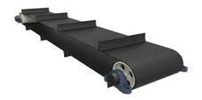
f) Conveyor Belt: Conveyors provide a dependable technique of transporting bulk materials in a continuous manner. When it comes to handling rate and total quantity warrant, this gadget is the most cost-effective. The type of conveyor used in this project is a chain conveyor. A machine having a moving chain is known as a chain conveyor. The conveyor bed is one of the components involved, and the size is determined by the requirements.
Figure 7: Conveyor Belt
g) Relay: A relay is a switch which is initiated or stopped by electricity. Many relays use an electromagnet to mechanically activate a switch, however solid state relays and other working principles are also used. Relays are employed when a lowpower signal is required to control a circuit (with perfect electrical isolation between the control and controlled circuits), or when multiple circuits must be controlled by a single signal.
Figure 8: Relay


D. Software Description The given below is the detailed information of the softwares used in this project. 1) Arduino IDE: The Arduino Software (IDE) includes a text editor for writing code, a message area, a text console, a toolbar with buttons for basic functions, and a series of menus. It communicates with the Arduino and Genuino devices by connecting to them and uploading code. Arduino sketches are programmes made with the Arduino software (IDE). These sketches were created with a text editor and saved with the.ino file extension. The editor allows you to cut/paste, as well as search for and replace text.. The message section indicates faults and provides feedback while storing and exporting. The Arduino Software (IDE) outputs text to the console, which includes detailed error messages and other information. The configured board and serial port are displayed in the window's bottom right corner. You may validate and upload programmes, generate, open, and save sketches, and open the serial monitor using the toolbar buttons. 2) Proteus: The Proteus Design Set is a proprietary software tool suite that is primarily used to automate electrical design.
Electronic design experts and technicians use the programme to develop schematics and electronic prints for printed circuit board manufacture. It was created by Labcenter Electronics Ltd in Yorkshire, England, and is accessible in English, French,
Spanish, and Chinese. The Proteus Build Suite is a Windows tool that allows you to record schematics, simulate them, and design PCB layouts. It comes in a variety of forms, depending on the size of the designs being created and the microcontroller simulation needs..An autorouter and basic mixed mode SPICE simulation capabilities come standard with every PCB Design product. The Proteus Design Suite's schematic capture feature is utilised for both simulation and design phases of PCB layout projects. As a result, it's an essential component that comes standard with all product configurations. 3) Eagle: EAGLE is a scriptable electronic design automation (EDA) application with schematic capture, printed circuit board (PCB) layout, auto-router and computer-aided manufacturing (CAM) functions. A schematic editor is included with EAGLE for creating circuit diagrams. Parts are defined in device libraries with the .lbr extension, while schematics are kept in files with the .sch extension. Parts can be stacked on many sheets and connected via ports. Board files with the extension .brd are saved in the PCB layout editor. Back-annotation to the schematic is possible, as is auto-routing, which connects traces automatically depending on the connections provided in the schematic. Gerber and PostScript layout files, as well as Excellon and Sieb &
Meyer drill files, are all saved by EAGLE. Because EAGLE's typical user base consists of small design firms and amateurs, many PCB fabricators and assembly businesses accept EAGLE board files (with extension.BRD) directly to output optimised production files and pick-and-place data. For editing, project administration, and customising the interface and design parameters, EAGLE provides a multi-window graphical user interface and menu system. The system can be operated using the mouse, keyboard hotkeys, or a command line embedded in the system. Hotkeys on the keyboard can be customised by the user.
Script files can include several repeating commands (with file extension .SCR). It's also feasible to use an EAGLE-specific object-oriented programming language to investigate design files (with extension .ULP). 4) Tinkercad: Tinkercad is a free online 3D modelling programme that runs in a web browser and is noted for its ease of use. It's a popular platform for producing 3D printing models as well as an introduction to constructive solid geometry for beginners.
Tinkercad builds models using a simplified constructive solid geometry method. A design consists of primordial shapes which are either "solid" or "hole" in form. By combining solids and holes, new shapes can be constructed, each of which can be assigned the solid or hole property. A built-in JavaScript editor allows users to create new form generators in addition to the standard library of primitive shapes.
E. Working To automate bottling operations, we should first understand what is happening in the bottling system. The bottle filling system's process is as follows:
1) Bottle Detection using Sensors: Bottles are held in place in their corresponding holders, which are attached to the input conveyor. The presence of bottles in the holder is detected using infrared sensors. The filling procedure is carried out based on the output of the sensors. To set the state of the bottles, a time delay is given. If a bottle is present at the start, the conveyor belt begins to move. The Arduino receives the outputs from these sensors, and the filling procedure for the bottles is controlled by this output. If all of the bottles are present on the input side, the sensor sends the corresponding output to the, which then turns
ON the corresponding pumps, allowing the filling operation to begin. If a bottle isn't present, the pumps for that bottle are turned OFF.
