Embedded Design Embedded Test
Getting on the bus How a general purpose oscilloscope can help with low speed serial bus debugging. By Tom Schmidt.
U
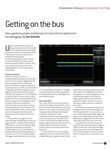
sing an oscilloscope to analyse and debug a low speed serial link is standard fare and today’s general purpose digital oscilloscopes contain a variety of features that allow the user to quickly verify a link or to troubleshoot a faulty system. Serial decoding packages are great tools for functional verification, but may not help to isolate a parametric problem on the bus. Also, users may not need to jump to the serial decode application in order to get a specific measurement. Is there any activity? When first turning on a system or troubleshooting a faulty board, a user will want to know if the bus signal(s) toggled when the switch was flipped or when a routine was executed. Roll mode, a simple but under used oscilloscope feature, provides a quick indication of signal activity without having to set up any trigger. Roll mode with peak detect provides confidence that signals as narrow as 500ps will be captured. Figure 1 shows a spi bus used to program a PLL circuit with three words during a power up sequence. The oscilloscope is set to roll mode at 200ms/div in peak detect acquisition mode. The peak detect circuitry is running at 4Gsample/s and storing min/max pairs at 250ksample/s. Power is applied to the board and the acquired data shows three separate packets of activity on all three bus signals. If the user desires to trigger in normal acquisition mode while looking for activity, the trigger type ‘OR’ – available in the InfiniiVision 3000-X series – can be used. With this trigger type, either or both slopes of any of the available trigger source can be enabled. For example, both rising and falling edge slopes on channels 1, 2 and 3 in fig 1 could be enabled. This trigger is useful because it is a functional
www.newelectronics.co.uk
Fig 1: Three packets of activity can be seen on three bus signals
‘or’ of channel edges, not a logical ‘or’ of trigger comparator states. This means a high level on an enabled channel will not mask triggers from other enabled sources. How many clocks? Often, users will want to count the number of clock cycles or edges in a packet from a serial bus that contains a dedicated clock such as spi, µWire or i2c. Fortunately, most general purpose ‘scopes provide two methods of getting this information. The first is to use the measurement system to count edges, pulses, or both. The captured burst will measure the number of clock cycles (and edges) of a long register programming stream; for instance, into an fpga. Automatic measurement markers provide confidence by indicating the first and last pulses. The other method is to use simple trigger sequencing. The user can measure the number of edges indirectly or trigger on a specific clock
edge within a packet by using this sequencing. For example, in the 3000-X series, the mode ‘Nth edge burst’ is useful for triggering on a non continuous clock signal. In this mode, the trigger system must first find a period of no activity on the signal. This time is set by the ‘idle’ control softkey, which has a range from 10ns to 10s. After the idle time requirement has been met, the trigger will occur on the desired edge count within the pulse stream. This count can be set from 1 to 65,535 by using the ‘edge’ softkey. The slope can be rising or falling. For example, the oscilloscope will trigger when the count is set to 540 or less, but not if the count is set to 541. For systems with continuous clocks, the ‘edge then edge’ mode can be used to trigger on a specific clock edge. In this mode, the trigger system sequences much like ‘Nth edge burst’ but, instead of looking for an idle, the system looks for an edge such as a chip select in a spi bus.
22 November 2011 37


