WATER
District metered areas: why accuracy matters By Vincent Favre
I
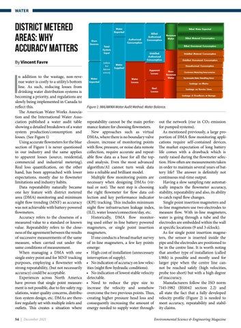
n addition to the wastage, non-revenue water is costly to a utility’s bottom line. As such, reducing losses from drinking water distribution systems is becoming a priority, and regulations are slowly being implemented in Canada to reflect this. The American Water Works Association and the International Water Association published a water audit table showing a detailed breakdown of a water system production/consumption and losses. (See Figure 1) Using accurate flowmeters for the blue section of Figure 1 is never questioned in our industry and the same applies to apparent losses (source, residential, commercial and industrial metering). Real loss quantification, on the other hand, has been approached with lower expectations, mostly due to flowmeter limitations and industry habits. Data repeatability naturally became one key feature with district metered area (DMA) monitoring and minimum night flow trending (MNF) as accuracy was not achievable with battery powered flowmeters. Accuracy refers to the closeness of a measured value to a standard or known value. Repeatability refers to the closeness of the agreement between the results of successive measurements of the same measure, when carried out under the same conditions of measurement. When managing a DMA with one single entry point and for MNF tracking purposes, employing a flowmeter with strong repeatability, (but not necessarily accuracy) could be acceptable. Experiences across North America have proven that single point measurement is not possible, due to fire safety regulations, water quality concerns, distribution system design, etc. DMAs are therefore regularly set with multiple inlets and outlets. This creates a situation where 54 | December 2021
Figure 1: IWA/AWWA Water Audit Method: Water Balance.
repeatability cannot be the main performance feature for choosing flowmeters. New approaches such as virtual DMAs, where there is no boundary valve closure, increase of monitoring points with flow, pressure, or noise data remote collection, require accurate and repeatable flow data as a base for all the topend analysis. Even the most advanced algorithm/AI cannot turn weak data into a reliable and brilliant model. Multiple flow monitoring points are necessary when designing DMAs (virtual or not). The next step is choosing the right flowmeter for flow data collection and key performance indicator (KPI) tracking. This includes minimum night flow infrastructure leakage index, (ILI), water losses/connection/day, etc. Historically, DMA flow monitoring used either in-line battery powered magmeters, or single point insertion magmeters. If one conducts a broad market survey of in-line magmeters, a few key points emerge: • High cost of installation (unnecessary interruption of supply). • No indication of accuracy on low velocities (night flow hydraulic conditions). • No indication of lowest stable velocity detectable. • Need to reduce the pipe size to increase the velocity and somehow overcome the two previous points. Thus, creating higher pressure head loss and consequently increasing the amount of energy needed to supply water through-
out the network (rise in CO2 emission for pumped systems). As mentioned previously, a large proportion of DMA flow monitoring applications require self-contained devices. The market expectation of long battery life comes with a drawback which is rarely raised during the flowmeter selection. How often are measurements taken in order to maintain several years of battery life? The answer is definitely not continuous real-time output. Having a slow sampling rate automatically impacts the flowmeter accuracy, stability, repeatability and also, its ability to catch rapid flow changes. Single point insertion magmeters and in-line magmeters use two electrodes to measure flow. With in-line magmeters, water is going through a tube and the electrodes are embedded within the wall at specific locations (9 and 3 o’clock). As for single point insertion magmeters, the sensor is inserted inside the pipe and the electrodes are positioned to be in the centre line. It is worth noting that another type of installation (called 1/8th) is possible and mostly used for larger pipe when the centre line cannot be reached safely (high velocities, probe too short) but with a high degree of inaccuracy. Manufacturers follow the ISO norm 7145-1982 (BS1042 section 2.2) and all state the fact that a fully developed velocity profile (Figure 2) is needed to meet accuracy, repeatability and stability claims.
Environmental Science & Engineering Magazine


